Children’s University 2024 with “Rubens to touch” in the Siegerlandmuseum

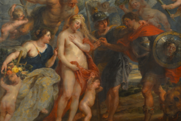
On September 24, Marios Mouratidis from the Fab Lab together with Dr. Philip Bojahr and Johannes Bade from the Siegerland Museum presented “A Touch of Rubens”, a transfer project funded by the Vice-Rectorate for International and Lifelong Learning.

While you are not allowed to touch most things in a museum, “A Touch of Rubens” is made for exactly that: it is primarily intended for people whose ability to see is limited. For them, there must be other ways to experience a museum exhibition. The painting “The Opportunity” by the painter Peter Paul Rubens was transformed by a 3D artist into a relief that can also speak. In this way, it tells its story without having to be seen. As part of this year’s fall season of the Siegen Children’s University, the children will learn how and with what the relief was made and can then try out the “talking picture” for themselves.

The barrier-free, inclusive communication of cultural education poses a particular challenge in the field of visual arts, as this genre is inherently subject to the primacy of sight and therefore excludes people with visual impairments. With the help of tactile interfaces and multimodal systems, visual works can be made accessible. Such systems are an important subject of research in the field of museum mediation and business informatics. Against this background, the Fab Lab has been conducting research in the field of Human Computer Interaction (HCI) for years, particularly in a museum context; for example, as part of the Zeit.Raum Siegen project (2016-2018) in the development of the interactive city model or, most recently, in a model test for the production of touch-sensitive facsimiles of archaeological finds for the Ginsburg in Hilchenbach.

In cooperation with the Siegerland Museum, these findings were incorporated into the development of a model application for the multimodal communication of paintings. The tactile relief for Peter Paul Ruben’s painting “The Favorable Opportunity” is intended to open up the wealth of symbols in the large-format work interactively and barrier-free. Individual pictorial elements (figures/objects) can be selected by pressing them, whereby audio content is output for explanation (text and sounds). Visitors will thus gain access to the painting in terms of content, narrative and atmosphere beyond mere touch, while retaining the spatiality of the pictorial composition (in contrast to an audio guide). Building on this, the aim of the project proposed here is to implement a model application for testing in visitor operations. This project will open up a further branch of research in the Fab Lab to investigate the barrier-free, inclusive communication of cultural education. Marcel Barion is responsible for the target group-specific and professional conception and production of the content (narrative and auditory processing of the painting). The 3-dimensional model was developed by Matthias Meyer. The exhibit was created by Philip Bojahr, Johannes Bade, Jonas Kosiahn and Marios Mouratidis. “This project clearly stands for the sustainable transfer of knowledge from the university to urban society,” explains Philip Bojahr, curator of the Siegerlandmuseum.

Train-The-Trainer Workshop for SIEGENIA trainees at the Fab Lab Siegen

From the 25th to the 28th of March, a technology camp will take place at the SIEGENIA Ausbildungszentrum, which we are organising together with the SIEGENIA GROUP and FRids e.V.. The technology camp will give pupils from regional schools the opportunity to learn the basics of 3D-modelling and 3D-printing.

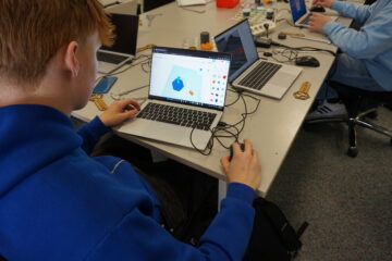
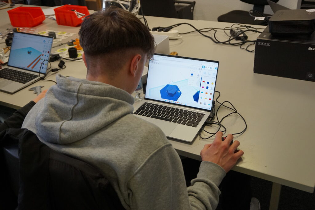
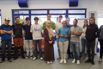
In order to provide the students with the best possible support, seven motivated trainees who work at SIEGENIA in the toolmaking and mechatronics departments were introduced to 3D printing in a train-the-trainer workshop here at the Fab Lab last week. Over the course of two days, our two colleagues, Marios Mouratidis and Jonas Kosiahn, taught the trainees how the technology works and how they can design and print their own models.

At the beginning of the workshop, the trainees were given an introduction to 3D printing and the modelling software TinkerCAD. Based on that, they were able to complete their first task: they independently modelled SIEGENIA key chains in TinkerCAD and then printed them.

The trainees then worked with a ball track system and designed and printed spare parts. The trainees had the task of recreating individual parts of the ball track system in TinkerCAD and then printing them using our 3D printers. Thanks to the practical approach in the workshop, the trainees were able to apply the knowledge they had acquired directly and are now ready for the technology camp!

We are delighted to be able to support STEM education in the region with our collaboration partners, the SIEGENIA GROUP and FRids e.V.. We really enjoyed the workshop and look forward to seeing how the trainees pass on their newly learnt skills to the pupils at the upcoming technology camp!

Project Day with the Gymnasium auf der Morgenröthe

On September 15, there was a lot going on at the Fab Lab: students from the Gymnasium auf der Morgenröthe visited us again. They spent the morning here at the Lab together with their teacher, Stefan Schramm, as part of a project day. The reason for this project day was the upcoming school fair celebrating the 50th anniversary of their school, for which each class had to prepare a stand.

The students had therefore decided to offer a wheel of fortune game with prizes. In order to plan and realize their idea here at the Lab, the students were divided into three groups.

The first group took on the task of designing and printing various prizes for the wheel of fortune game. This is where our 3D printers came into play. Different key chains as well as shopping cart chips were printed with the help of our 3D printer farm.

The second group designed and built the wheel of fortune itself. It was produced on our large CO2 laser cutter. The last group had the equally important task of documenting the entire day. The Lab Tour and the 3D printing process as well as the laser cutting, everything had been documented in the form of a video. You can watch the video here:

Overall, it was a successful project day with amazing results! It was great to see how committed and creative the students were in mastering the tasks and how well they worked together as a team. We are happy to have been able to support the students in their preparations for the school fair celebrating the 50th anniversary of the Gymnasium auf der Morgenröthe. We hope that the fair was a great success!

User-Story: Realization of a Planning and Development Project at the Fab Lab

Four students realized their planning and development project in the Fab Lab as part of their studies. This type of project is offered as a course as part of the Mechanical Engineering Program of Faculty IV at the University of Siegen. In this course, students work in groups on innovative technologies and concepts, which they present in a plenary session and document in a final report.

The goal of this project was to design a test rig for rubber bearing measurements in the chassis that can test all six degrees of freedom, since the current test rig of the Institute of Automotive Lightweight Design at the University of Siegen is not capable of doing so. The students focused on measuring U-bearings and RU-bearings.

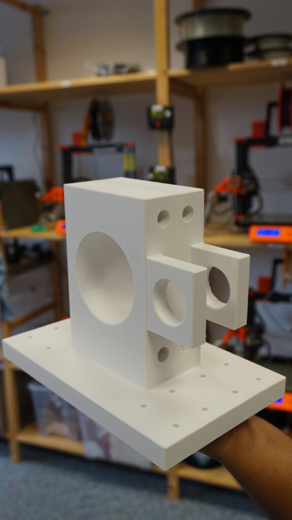
In order to be able to realize the concept they developed, they needed bearing supports that would hold the various bearings when subjected to the test forces. To do this, they developed a model for a U-bearing support and an RU-bearing support and then printed them three-dimensionally using one of our Prusa printers in the Fab Lab.

The respective bearings can be attached to the support with the help of four screws. In order to be able to screw the bearing supports to, e.g., a base or adapter, they have eight holes on each side. This allows them to withstand any load, whether translational or rotational. Both bearing supports can be mounted to the required motor – linear lifting cylinder or three-phase motor – depending on the spatial direction to be measured, and can be screwed to necessary aids such as rails, rollers, an adapter or a rotatably mounted table.

On the drawing you can see an exemplary test rig. This shows how the printed bearing supports, developed by the students, can be used in a translational measurement with the linear stroke cylinder and in a rotational measurement with a three-phase motor.

Test rig for the translational measurement (linear stroke cylinder) and the rotational measurement (three-phase motor)

We are happy that the Fab Lab can support students in their studies. So, if you also have a project in mind – whether as part of your studies or personal – just come by during our opening hours!

“We have 300 computers in the basement, do you want them?”

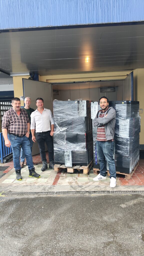
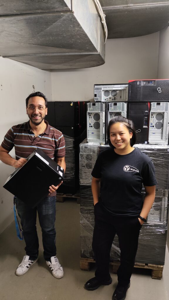
Of course we want them: 6-core i5 CPUs, M.2 SSDs and 8 GB DDR4 Ram are a good basis for an office or gaming computer. As you know, we have been getting more and more involved in STEM education since last year. So this calls for a cool format where we can dismantle computers, assemble them back together and then give them to participants for free. Thus, we were happy to accept the offer.

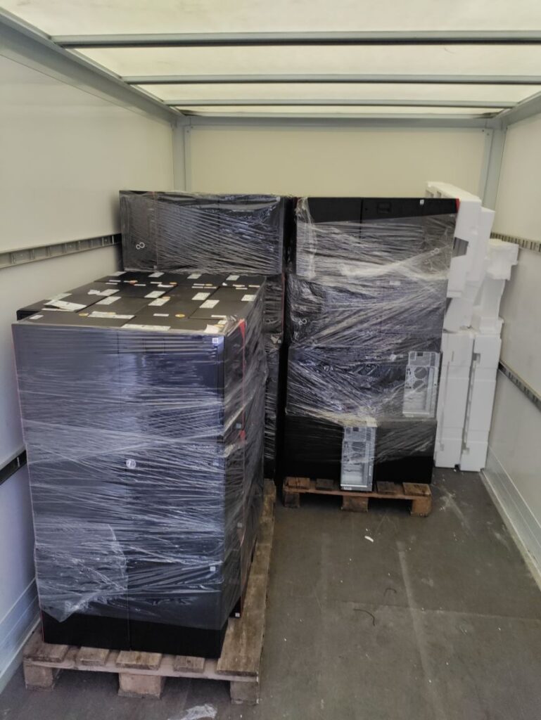
But how do we transport 300 computers to the Fab Lab? That’s not only 1,800 CPU cores, 2,400 GB Ram and 150,000 GB memory in total, but also 2.1t total weight…
The Lions Club Siegen and the SIEGENIA GROUP were kind enough to help us. “We do not have a truck available, but we will rent one for you.”, said Wieland Frank, owner of SIGENIA GROUP. Two employees also came to support. Thanks again!

Now we are planning a new workshop series that (hopefully) launches in October:

“Build your own computer” (just a working title, suggestions are welcome).

The idea: young participants take apart computers with us, we look at the components and how they work and then reassemble them together. Afterwards an operating system will be installed and at the end the participants can take the computers home.

We can use your support:

  • Helpers to support the workshop implementation,
  • 300 mice, keyboards and/or monitors (could be used, but should be working and clean)

Schools are welcome to contact us. We heard that a few computer rooms here and there could be renewed.

We would like to do some research on the workshop as part of our EnvironMINT project to analyze the conditions for success of good STEM education in more detail. How can workshops be designed in an appealing way – especially to get young women and girls interested in STEM topics?

History lesson on STEM activities of the Fab Lab
With FAB:MAKE, we were able to purchase hardware that allows us to carry out workshops with smaller groups. As part of EnvironMINT, we are investigating the conditions for success of good STEM education with our partners (FAU Erlangen-Nuremberg, HS Rhein-Waal). In cooperation with Digitalum Bus, we are able to bring the topics mainly to the more rural areas in the old district of Wittgenstein.

From time to time, school classes also visit us and we carry out project days. But that’s not quite enough for us. We would like to build a strong network in Siegen-Wittgenstein with actors in the region: Schools, associations, companies, MINT partners and many more.

A lot of strong partners are already involved: Fab Lab Siegen, Digitalum-Wittgenstein gGmbH, FRids e.V., DRK Kreisverband Siegen Wittgenstein e.V., Bildungszentrum Wittgenstein, Lions Club Siegen, companies such as SIEGENIA GROUP and Pollrich GmbH, but also some schools as well as the Siegerlandmuseum.

We hope that the network will continue to grow and are excited about what we will achieve together in the future!

Erweiterung des Rotationszugbiegens zu einem teilkinematischen Verfahren mit reduzierten Werkzeugflächen

„Wer Kunststoff kennt, nimmt Stahl!“

Ein altbekannter Spruch in unserer von Stahl geprägten Region. Aber wie viel Stahl braucht ein Produktionswerkzeug eigentlich wirklich? Diese Frage haben wir vom Lehrstuhl für Umformtechnik (UTS) uns im DFG Projekt „Erweiterung des Rotationszugbiegens zu einem teilkinematischen Verfahren mit reduzierten Werkzeugflächen“ gestellt.

Verfahren und Werkzeuge

Rohrbögen werden im industriellen Produktionsalltag mittels Rotationszugbiegen gefertigt. Beim Rotationszugbiegen wird das Profil um eine innen liegende Biegeform gebogen. Damit das zum Biegen notwendige Moment aufgebracht werden kann, wird das Profil einseitig durch den Gegenhalter geführt. Das andere Ende des Profils wird mit der Klemmbacke an die drehbar gelagerte Biegeform geklemmt.

Schematische Darstellung des Rotationszugbiegens (links). Prozessvideo (rechts)

Aufgabe im DFG Projekt war es, die bestehenden formgebunden Werkzeugelemente des Rotationszugbiegens geometrisch aufzulösen und zu vereinfachen.

Dies ermöglicht:

  • erhöhte Flexibilität des Umformprozesses
  • wirtschaftliche Produktion kleinerer Losgrößen
  • individualisierte Produkte

Über eine Flächenreduktionsmethode wurden schräg angestellte Kontaktflächen statt der bisherigen, voll umschließenden Werkzeuge abgeleitet.

Zum direkten Vergleich mit der konventionellen Bauform wurden diese neuartigen Werkzeuge zunächst aus Werkzeugstahl hergestellt. Mit dem Ziel der Flexibilisierung des Rotationzugbiegens können die geneigten Werkzeugflächen vertikal verstellt werden, so dass Rohre mit Durchmesser von 25 mm und 30 mm um 90° gebogen werden können. Untersucht wurden Rohre aus den Werkstoffen Edelstahl und Messing. Die Wanddicke betrug 1 mm und 2 mm.
Ergebnisse

Im Vergleich zu den konventionellen Werkzeugen ist die Deformation der Rohre stärker ausgebildet, und nimmt mit abnehmender Wanddicke zu.

Deformationsvergleich nach 90 ° Biegung: Unterschied konventionellen zu vereinfachten Werkzeugen (a). Abweichungsscan der gefertigten Rohrbögen (b)

Alle Proben weisen eine Falte am Innenbogen vor der Klemmbacke auf. Rückzuführen ist dies auf die fehlende Unterstützung im Biegeformgrund, was sich auch in den Simulationen in abgeschwächter Form zeigte und für die Qualität einen akzeptablen Umfang des Toleranzmerkmals darstellt.

Darf es eine Schicht mehr sein?

Nach den positiven Projektergebnissen mit dem reduzierten Werkzeug haben wir im Anschluss des Projekts gedacht: „Wer Kunststoff kennt, der nimmt auch Kunststoff!“

Also wurden alle Werkzeugteile auch aus Polylactide (PLA) beim Fab Lab Siegen auf 3D Druckern additiv gefertigt. Die Flexibilität des Projektes mit reduzierten Werkzeugflächen zu biegen, wird durch den additive Tooling Ansatz weiter gesteigert, da so vereinfachte Werkzeugeinsätze on-demand aus kostengünstigerem Kunststoff gedruckt werden können.

Aus Sicht des Profils erreicht man eine bessere / glattere Oberfläche. Auch die Faltenausprägung liegt in gleicher Größenordnung. Aber wer will schon gerne Falten haben? Ein Blick auf den im Innenbogen liegenden Faltenglätter zeigte, dass dieser der hohen Belastung nicht standgehalten konnte.

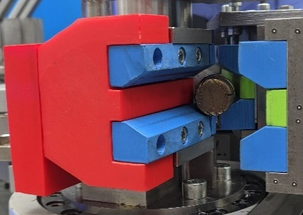
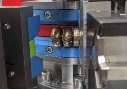
Flächenreduzierter Werkzeugsatz aus PLA zum Rotationszugbiegen von Metallrohren (oben)
 
Deformationsvergleich: Unterschied konventionellen zu PLA Werkzeugen (unten)

In einer Anpassung des Werkzeugkonzepts konnte abschließend ein Rohr mit vergleichbarer Qualität wie mit den konventionellen Werkzeugen gebogen werden.

Bleibt noch die Frage wie viel Profile kann mit einem PLA-Werkzeug gebogen werden. Wenn du dies beantworte willst, komm zu uns.

Hier noch mal ein fettes Dankeschön an das Team vom Fab Lab Siegen für die Unterstützung.

Production of a prototype for a bending machine (Master thesis mechanical engineering)

As part of my master’s thesis at the Chair of Micro- and Nanoanalytics in cooperation with the Chair of Forming Technology at the University of Siegen, I developed and subsequently commissioned a bending machine for plastic forming in the scanning electron microscope.

The bending machine will be used to perform three-point bending tests to investigate the crack initiation of bent specimens in order to better utilize materials in bending forming. Forming processes are used in the manufacture of products in many areas of daily life: Cars, aircraft, ships, piping, sheet metal forming and many more.

For a detailed examination of the bending specimens during the bending test, I built the bending machine to fit the scanning electron microscope (SEM). Since there is little space available in a scanning electron microscope, the machine had to be relatively small and light – it fits on the palm of a hand. Initial bending tests in the SEM have already been carried out.

Rapid Prototyping

During the design phase, I used 3D printing as a rapid prototyping process. Compared to machining processes, this method has the advantage of fast production of parts based on CAD models. The first 1:1 scale prototype was designed and 3D printed during a planning and development project, also as part of my studies.

Especially at the beginning of the project, it was important to quickly get a good idea of the real dimensions of the components to be manufactured later. Thanks to the friendly support of the Fab Lab in the person of Fabian Vitt, the required components were printed quickly and without any problems. Thanks to the friendly support of the Fab Lab in the person of Fabian Vitt, the required components were printed quickly and without any problems. In this way, all those present can get a very good picture of the shape and details of the component that will later be manufactured through the 3D printouts. This is less possible with the otherwise often used printed construction drawings. 3D prototyping can lead to new fitting ideas and facilitate the identification of necessary optimizations.

A short animation video of the bending process:
https://lmn.mb.uni-siegen.de/in-situ-em/

Soviet hand drill repair

Pre Story

My father bought the thing at the flea market sometime. The price of 5 rubles (Ц. 5Р.) is incorporated in the handle, because at that time in the Soviet Union there was the planned economy and you could get a pack of butter for the same price in the big whole country.

Problem

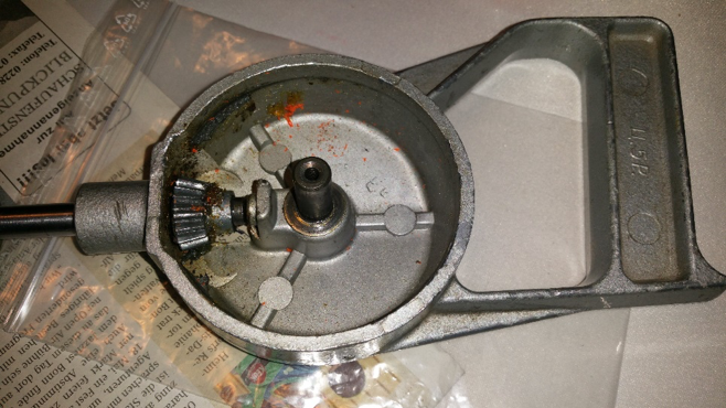
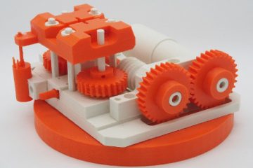
The drill always did its job. It is particularly suitable for small jobs and you can dose the torque manually. Only at some point the drill got stuck somewhere and my father exerted too much momentum on the big bevel gear until a few plastic teeth sheared off, rendering the thing useless. The old bevel gear consisted of two parts: The front side with the teeth was made of a plastic casting and the back side was made of some kind of metal, which was somehow connected to the plastic (unfortunately no photo). So a new bevel gear was needed.

Solution

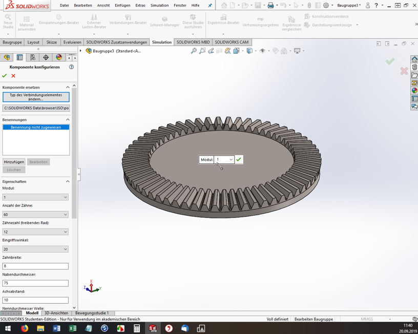
First, the teeth of the bevel gear had to be counted. There are 60 teeth. The driven bevel gear has 15 teeth, so there is a ratio of 1:4. In addition, all dimensions, such as the height of the teeth, their width and the bore diameter of the bevel gear had to be measured with a caliper gauge. The problem: the teeth are not simply arranged in a straight line, and their “focal point” is somewhere in the air. They are also wider at the outermost diameter than at the inner diameter of the bevel gear. So the geometry is a real challenge and you can’t just build the thing with a CAD program if you’re not a professional.
But what to do? Fortunately, I happened to come across a solidworks tutorial on the internet. It shows how to create configurable standard parts using the solidworks (SW) design library. And that worked well!

Procedure

Open Solidworks, open any assembly and throw out all the parts. Somehow it didn’t work out any other way for me. Then, on the right side of the screen, open the construction library and shimmy through the tree. Toolbox, ISO, power transmission, gears, degree bevel gear (driving).

Solidworks

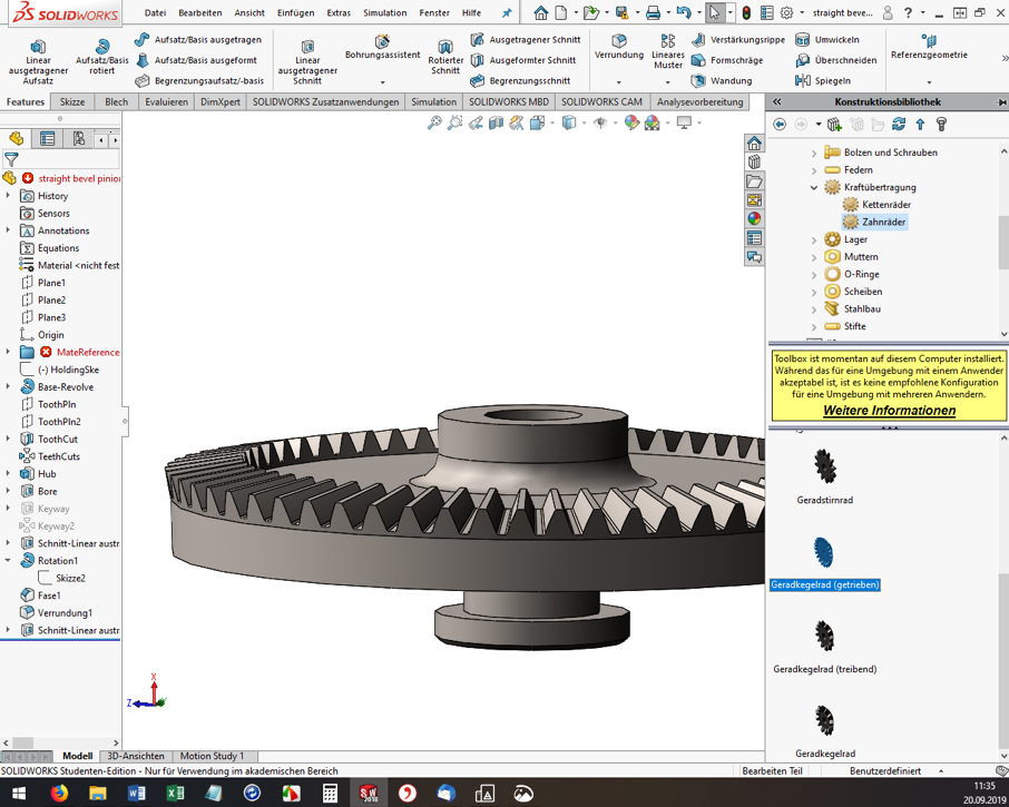
For me, the ISO standard matched well with my Soviet part. Then the “Degree bevel gear (driving)” must be dragged and dropped into the assembly window. Now the “Configure component” dialog opens on the left. The module, the number of teeth, the pressure angle, etc. can be set. Here you have to experiment, have the bevel gear with the green check mark built again and again and measure it. (Tip: If you click on a component edge, the bottom info bar of SW conveniently shows the measured length directly).

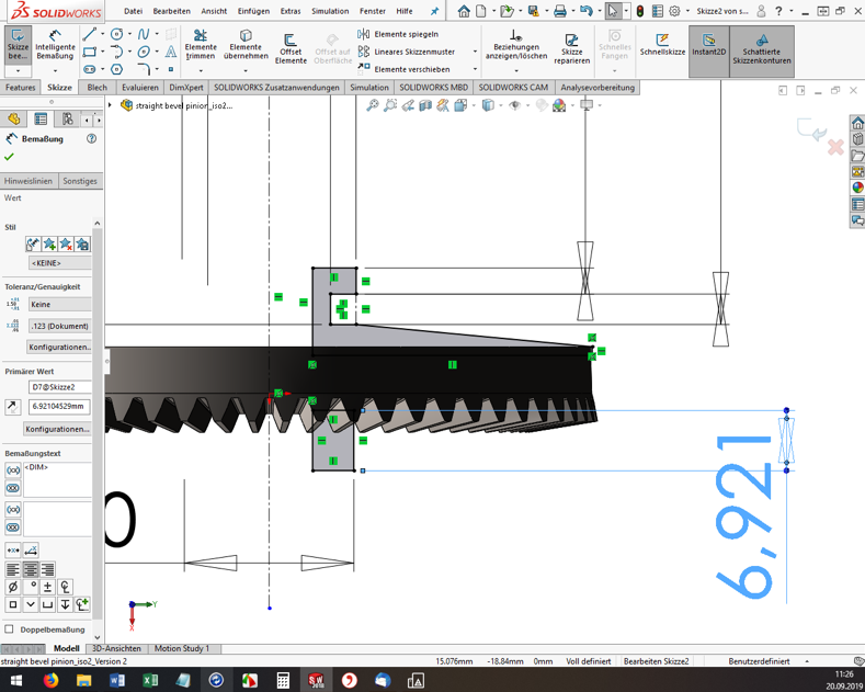
SolidWorks-2

However, you cannot specify all dimensions and geometry properties in the configurator. And here’s where it gets a little tricky. If the tooth geometry of the blank created fits so far, the rest must now be added manually. I used the function “Attachment/Base rotated” to build a created sketch as a body of rotation to the blank (see screenshot). Again, I had to measure the old bevel gear over and over again.

SolidWorks-3

Once you are satisfied with the part, you need to export it to *.STL format for 3D printing. And off we go to the Fab Lab Siegen! Here Fabian helped me out, showed me the 3D printers and started the printing. Thanks a lot! 😊

Result

The first print was unsuccessful (of course). In 3D printing, for example, the holes are always slightly smaller compared to the model. The teeth were also too small, so that they could not engage deeply enough with the opposing teeth. These teeth also sheared off during initial attempts. In addition, the bracket for the crank was a bit too thin and is therefore broken off.

Gears printed

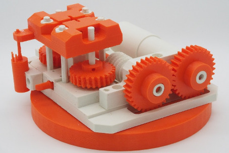
Drill machine open

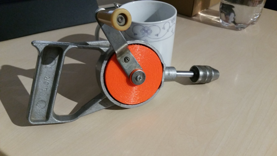
But now it was possible to measure the printed bevel gear and improve the dimensions in SW and finally start a second attempt. However, the second time it went better than expected and the bevel gear installed beautifully. The hand drill runs very smoothly and if any problems should occur in a few years, I’ll just print out the bevel gear again 😉 .

Drill-machine-composed-1

Drill-machine-composed-2

A Child’s Book, or: Saving Plastic, Starting 3D Prints New

During the summer semester 2020, there was a printer in the Fab Lab that was constantly cancelled for testing. The printer with the name “Hades” had to serve as a test object for a children’s book. But what does a children’s book have to do with highly experimental, plastic-saving techniques? Let’s lunge a litte bit.

Earlier this summer semester, I decided to develop a children’s book for 3D printers. Together with my fellow student C. Ajiboye, this became a manual that tells a story on one side, one of Ursa, a girl exploring 3D printing through “Learning By Doing.” On the other side, there were explanations of how Ursa finds problems and what solutions it gives for each of them.
But the last page was special:

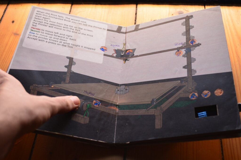
A WLAN-enabled (ESP32) microcontroller was embedded in this page. This one could feel touches via its touchpins. I then soldered these pins to copper surfaces and hid them under the page. One laser cut later, the copper surfaces could be seen shining through.

Thanks to these surfaces it was now possible to give commands to the ESP32. And thanks to the Octoprint servers, it was then possible to give commands to the printers. Yes, you read that right, this little book has a remote control for a 3D printer built in.

But What is the Point of All This?

Restarting a 3D print is not an easy task, so far there is not a single Octoprint plugin that dares to do this. The result is that when a print fails, which the sensors do not notice, a lot of time, sometimes days, and also up to kilos of plastic are lost. This book was intended to prevent that.

A book has many advantages: it’s quickly at hand, it’s often where you want it, and the software doesn’t change much. It is also lighter than a laptop and thus handier to use. What’s more, you don’t have to boot it up or preconfigure it. The interface is simply there.

But How do You Restart a Print With a Book Now?

A 3D print is stored in machine code. This “code” is written line by line and executed line by line afterwards. So a group of lines represents a layer, because a 3D print is done layer by layer. If a 3D print fails at one point, the commands could be executed again from this point. In the file, as well as in the real print, an exact height is defined for this. You could measure this height, but neither with the eye nor with a ruler you can find it exactly. With the 3D printer itself, on the other hand, you can find the exact height. Like calibrating old 3D prints, you can now use a piece of paper and the tip to determine to within 0.1mm where a print failed. So, with the book in your hand, you move the nozzle exactly over the pressure, lower it very slowly, and try to feel with a piece of paper placed in between when the nozzle touches the pressure.

The printer then knows exactly where this nozzle is located, if it is still referenced. Based on this height, the code is then split, the necessary initial steps are executed and then the printer prints again as if it had never stopped.

I Want This Too

After this semester I found the time to develop this project as a plugin for Octoprint. So you don’t need your own book and you can try it out in the web interface. But ATTENTION! This plugin is highly experimental and has also once caused damage to a 3D printer. I do not make any guarantees or take any responsibility for future damages and advise to always hover with your hand over the emergency switch until the first layer prints again and you are sure that the printer is working on the correct line.

Yours, Gerrit.

A Suitcase Filled With Heart

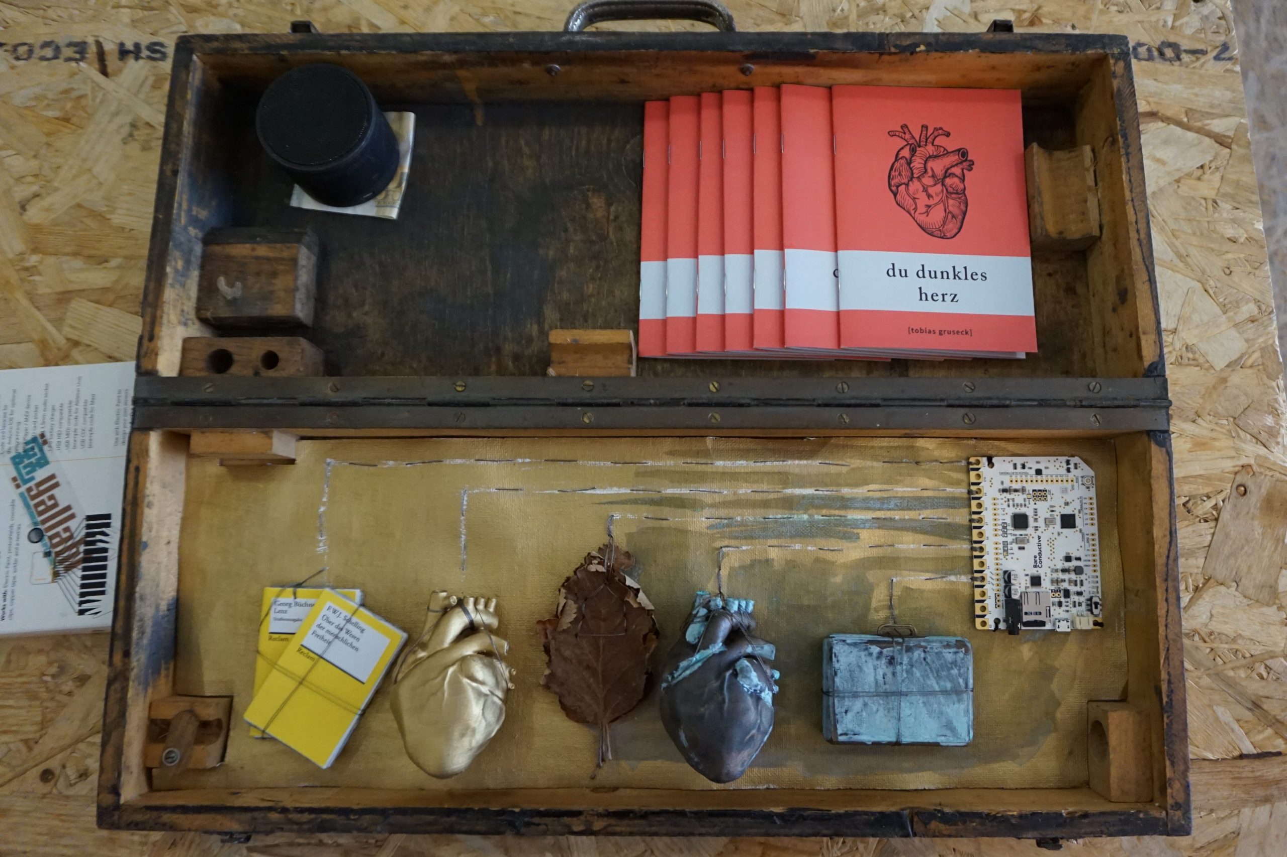
At the beginning there is a story. A reappraisal of feeling, put into words and released into the world. “Du dunkles Herz” (“You dark Heart”) by Tobias Gruseck comes as an appealing red booklet and is a story about a suitcase full of money that darkens hearts. But promoting literature depends on more than the content of the text. A myth around it is good, maybe an eccentric author, a scandal. Or a suitcase, in it: hearts. If you touch one of the hearts, or the oak leaf next to it, you suddenly hear voices. Text passages that match the object touched resound softly and wonderfully recited from the case and make you want to listen to the story.

A story is told here with multimedia and attention to detail

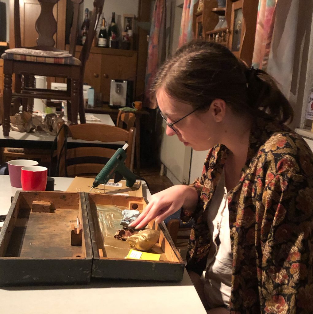
Jenny and Simon took on the presentation of the work and built the suitcase. Wired inside is a touch board from Bare Conductive® that is connected via conductive yarn to things that are historically significant and, in some cases, 3D printed. Touching the thread closes the circuit and the text passages stored on the chip and previously recorded with virtuosity are played.

Literature as a haptic experience

All this was first presented in Bad Säckingen at “Kunst trifft Handwerk,” an annual outdoor event at the picturesque Trompeterschlößchen, where Germany and Switzerland bundled streams of tourists before the pandemic moved in. The title of the event also fits perfectly with this haptic project, which combines literary effusion with gifted tinkering. Currently on display at Fab Lab Siegen.