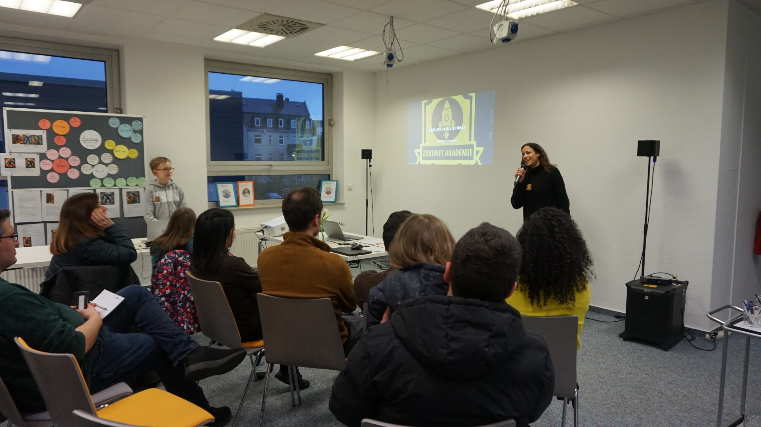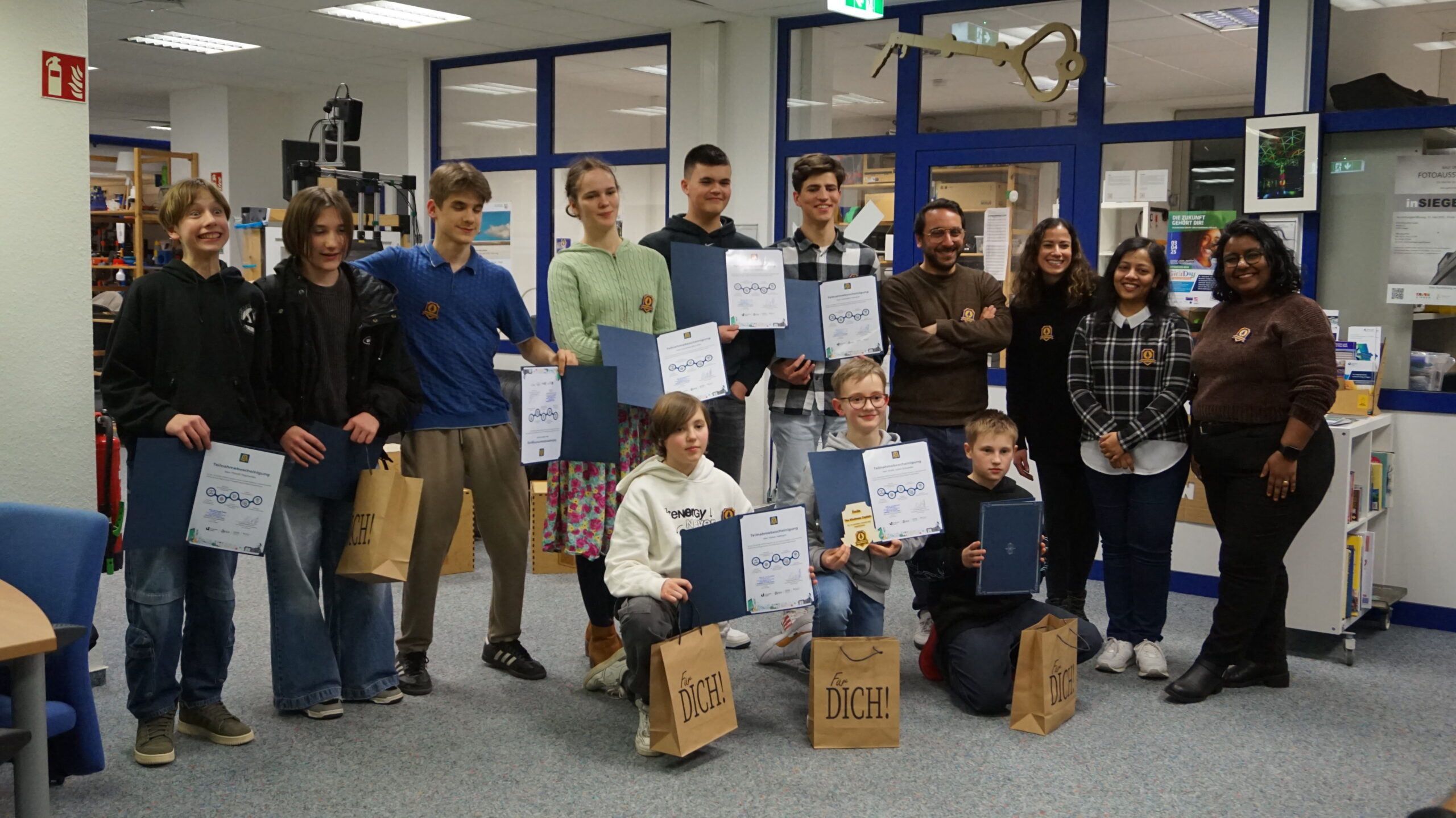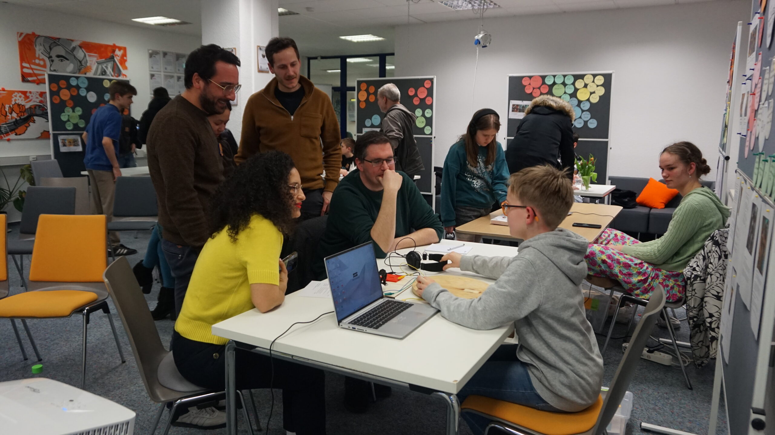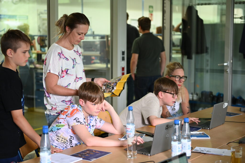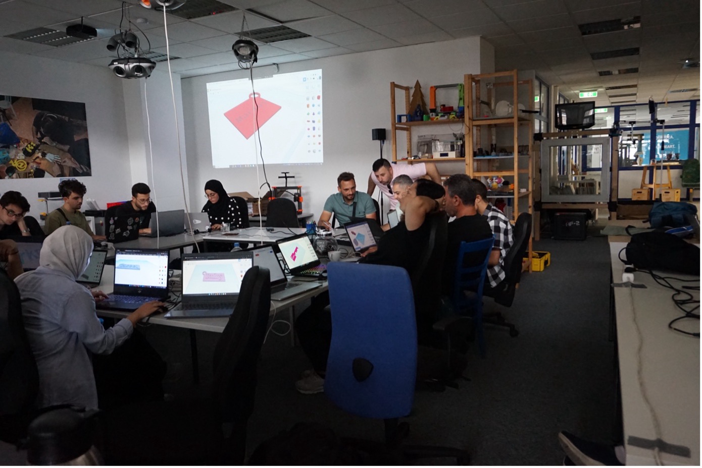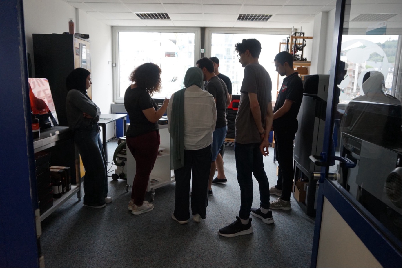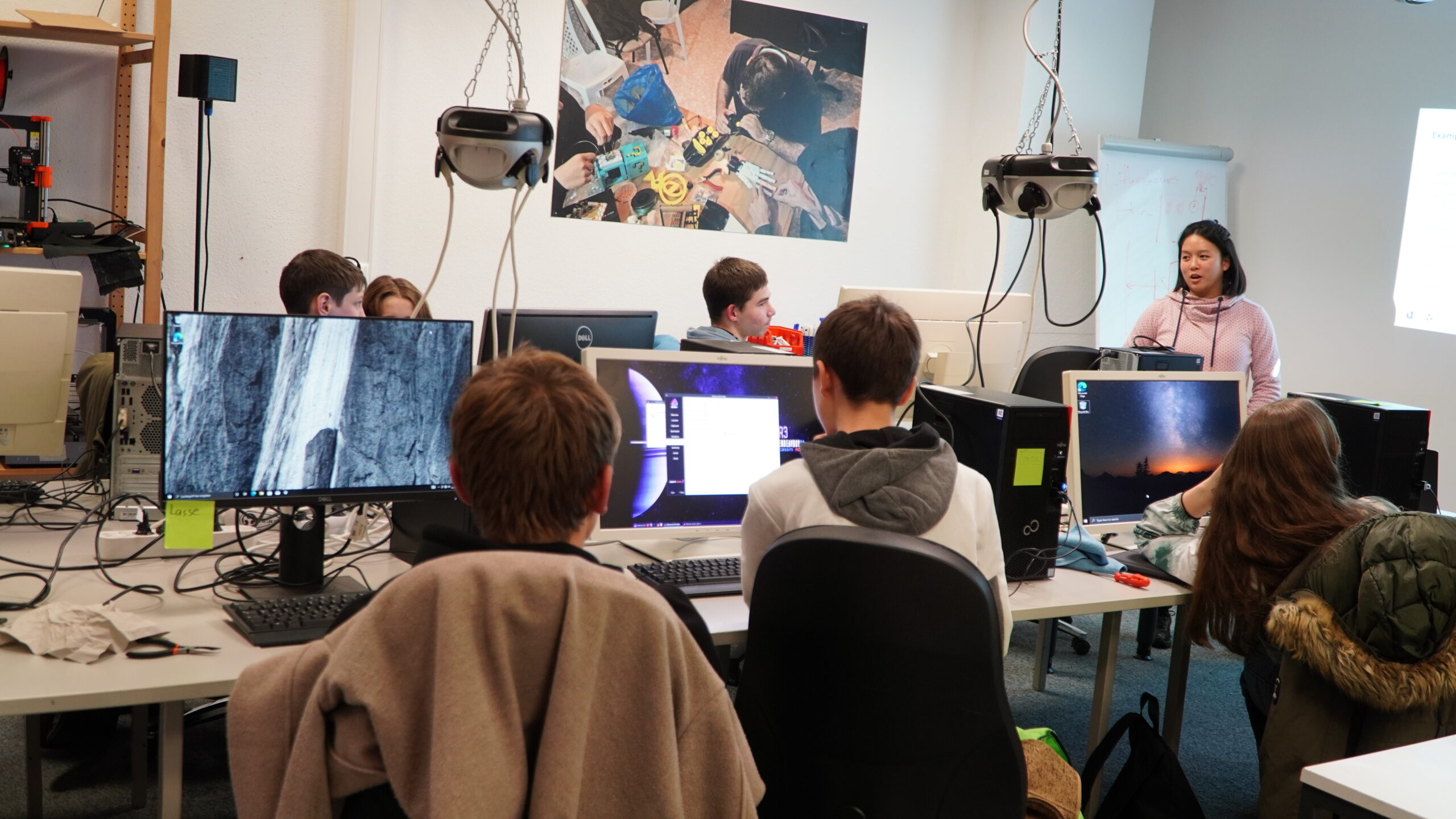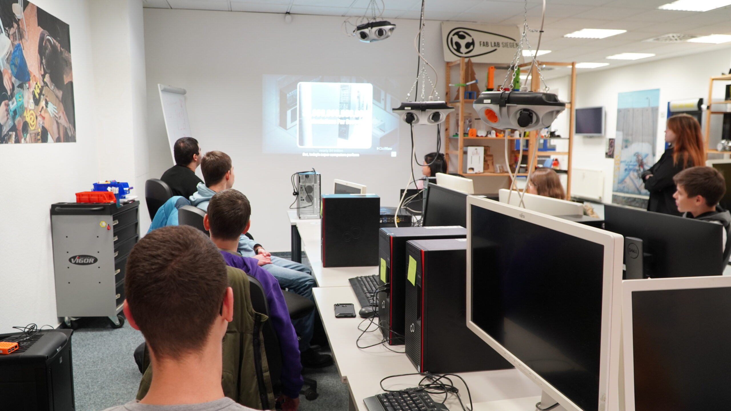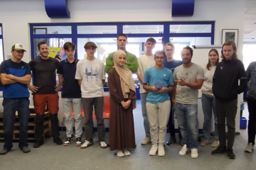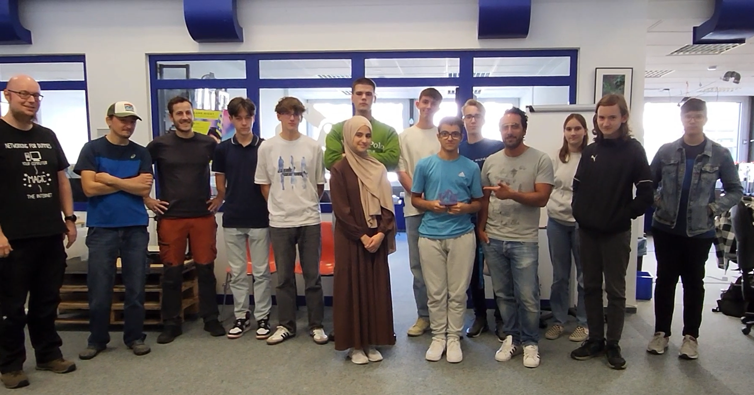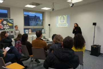
After months of intensive workshops, the Zukunft Akademie celebrated its final event at the Fab Lab of the University of Siegen. Ten talented children showcased their creative final projects in an interactive project gallery.
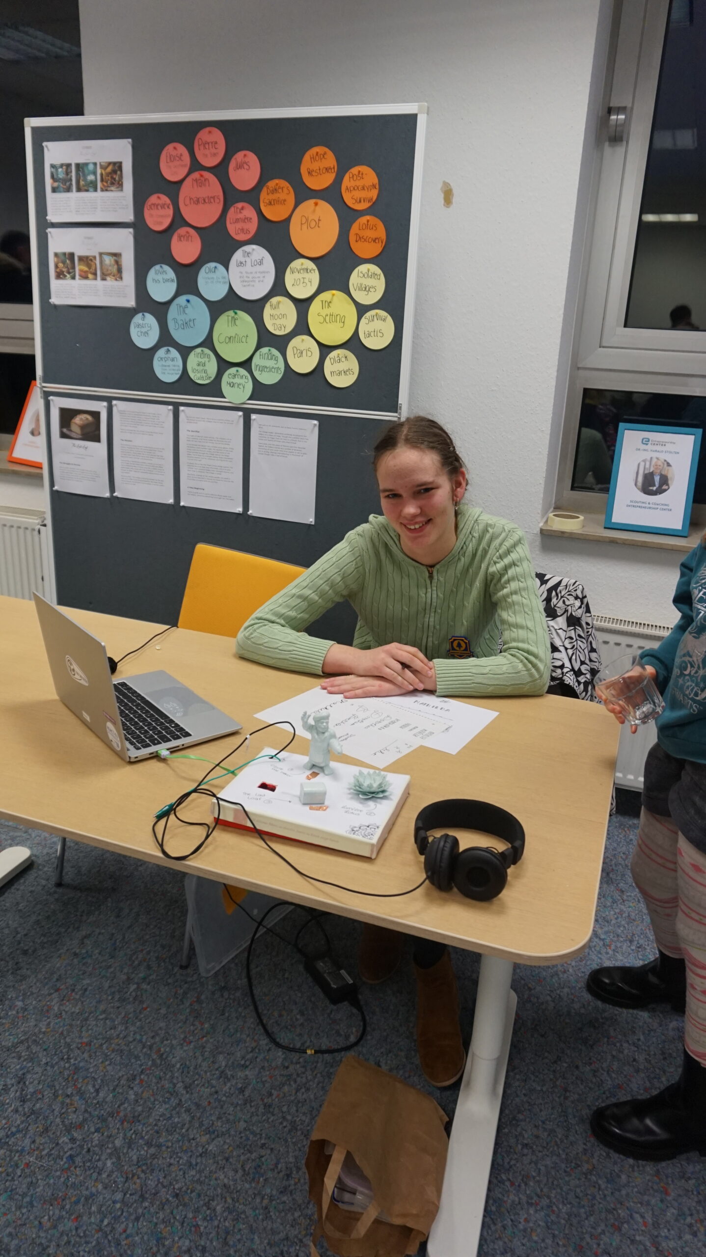
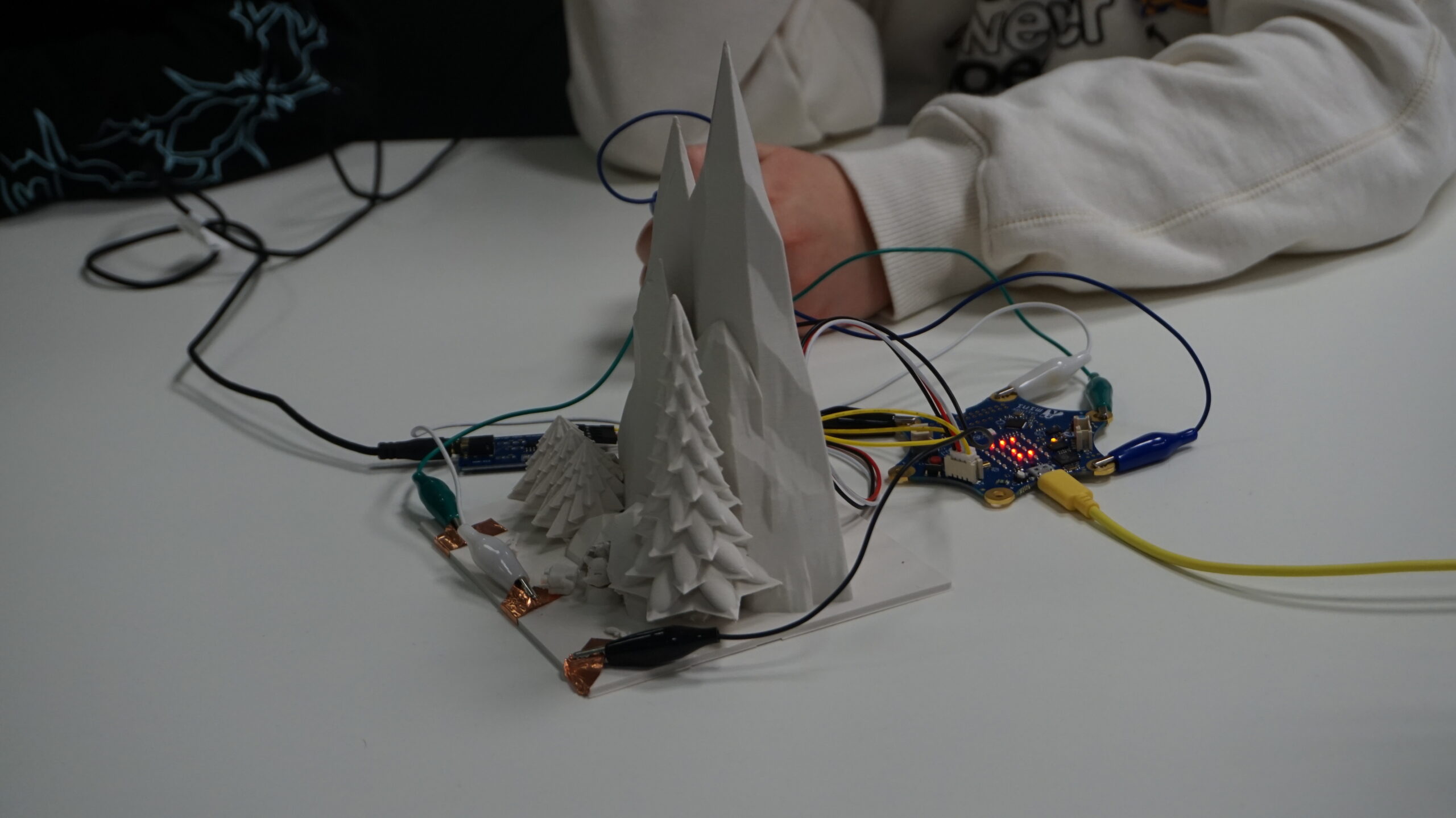
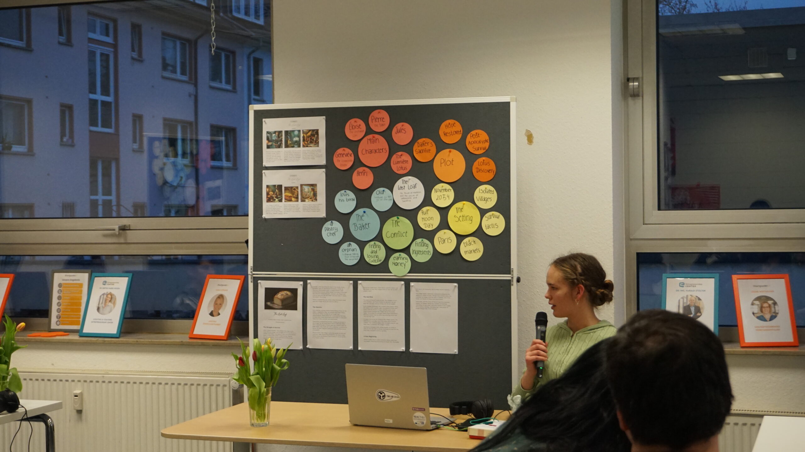
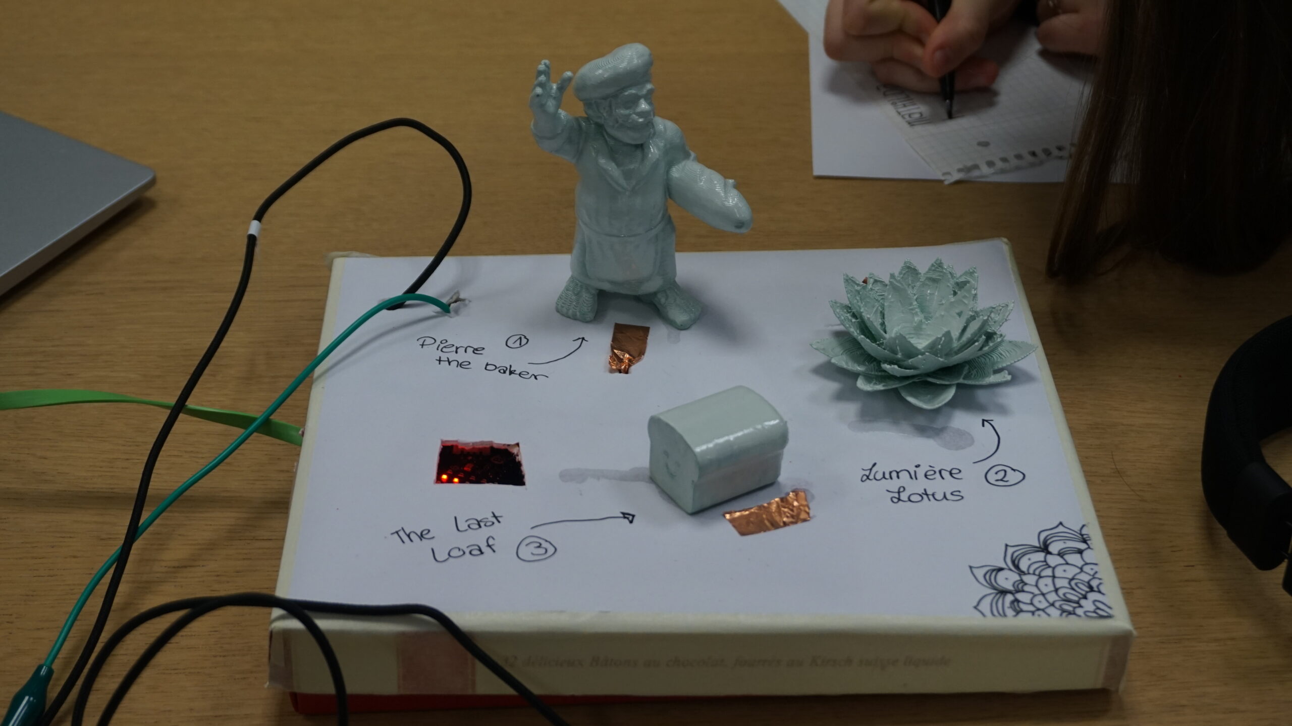
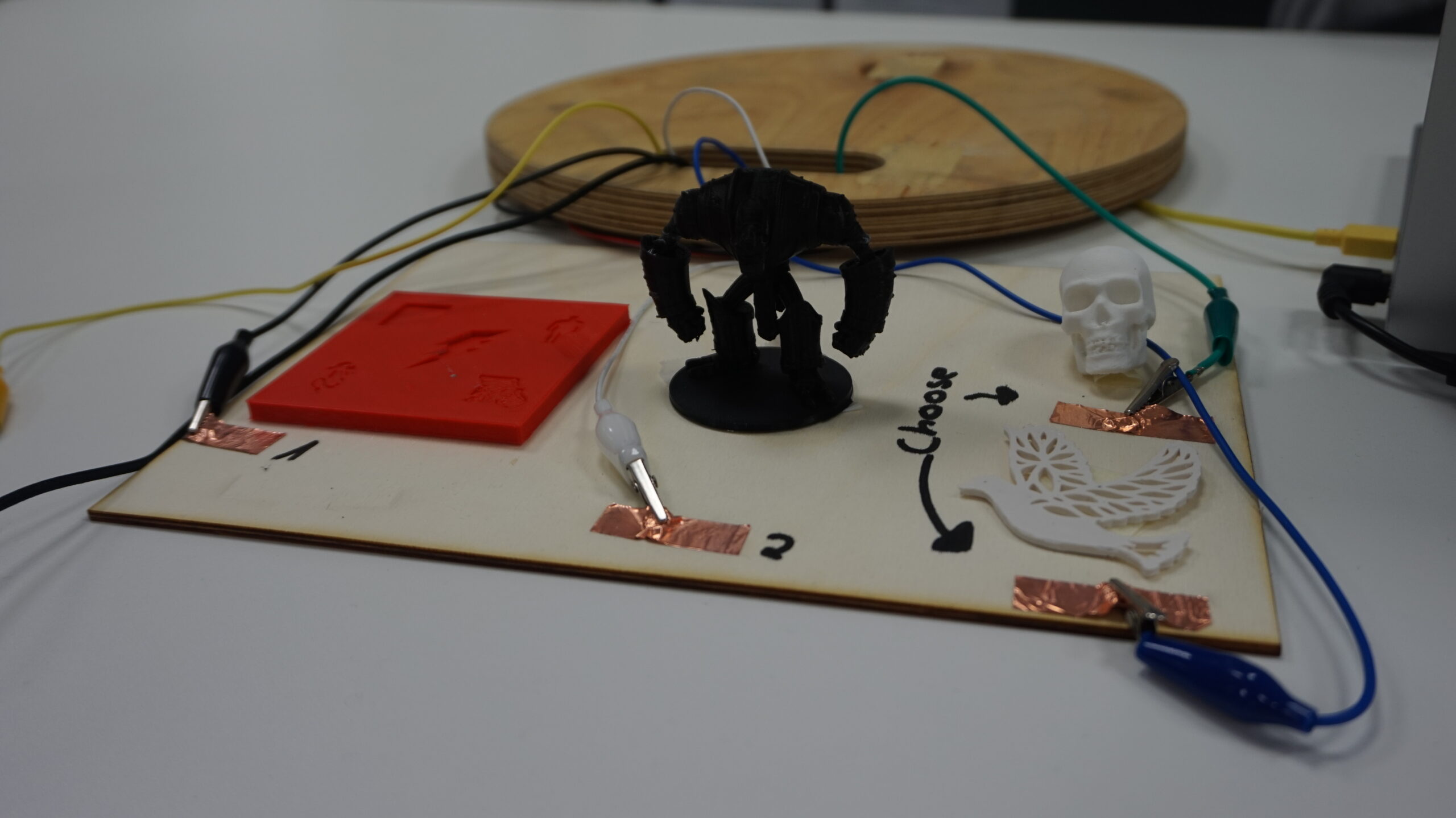
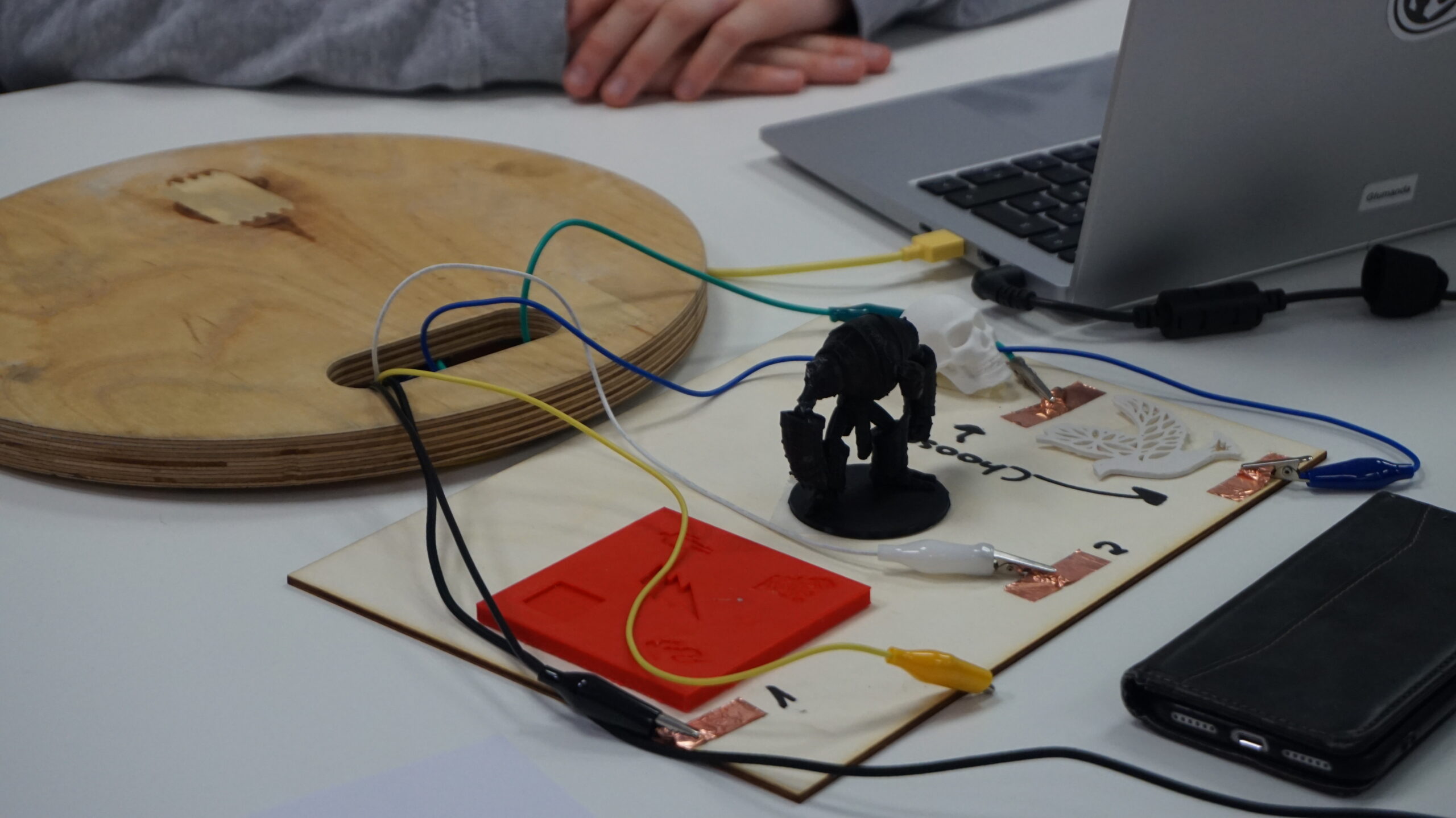
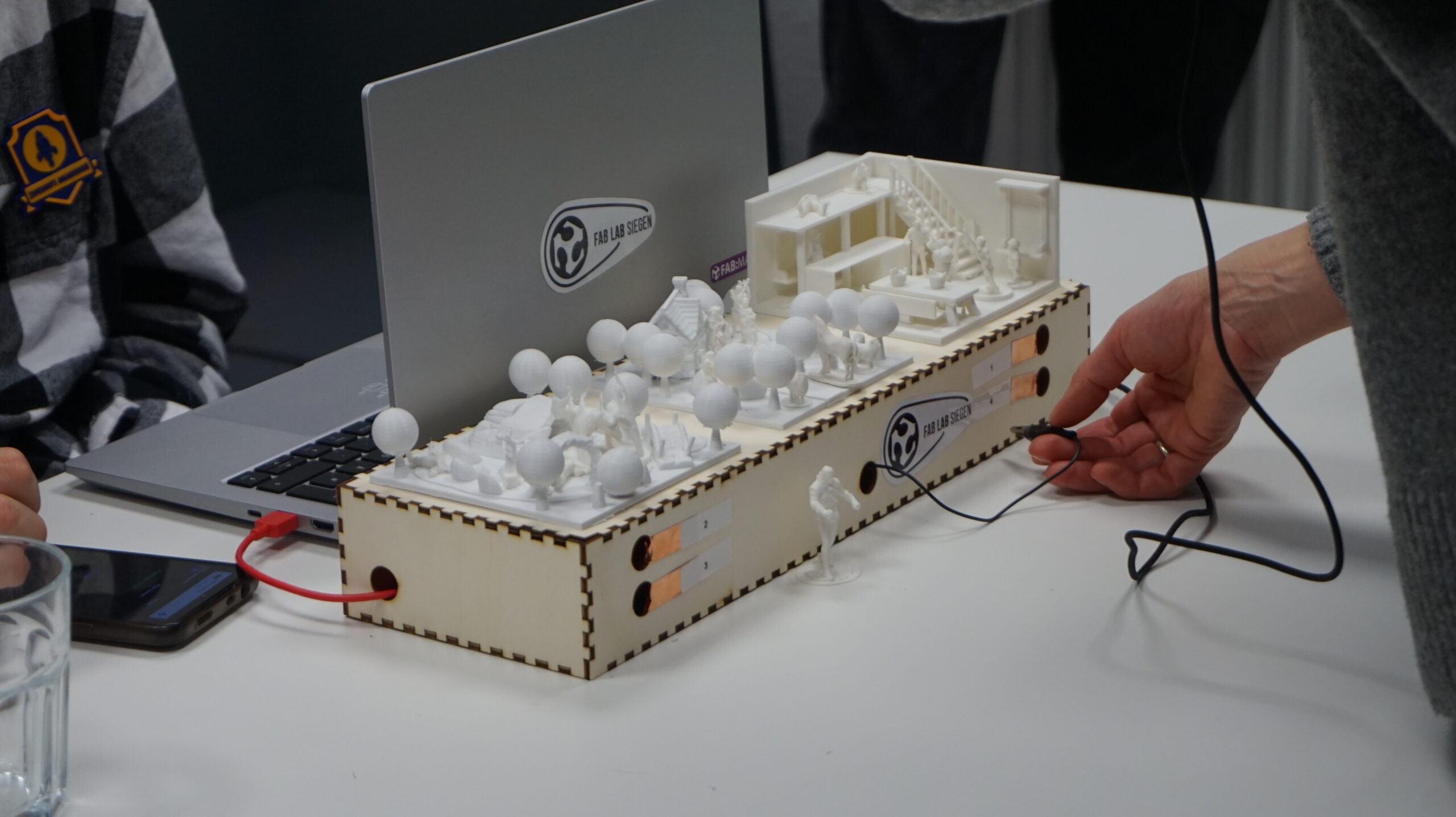
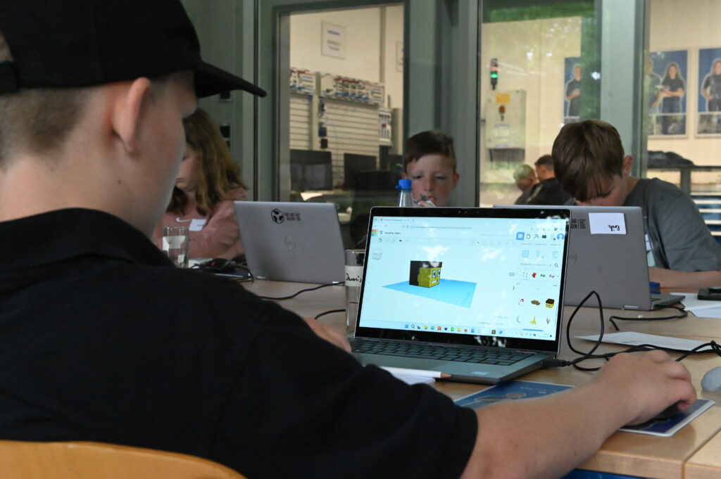
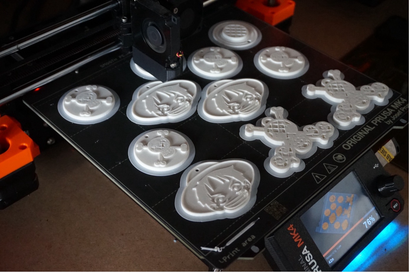
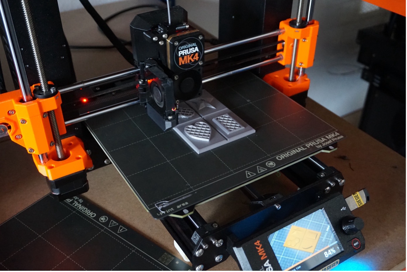
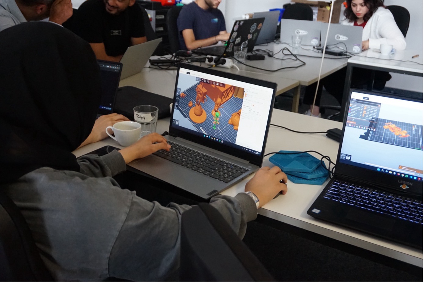
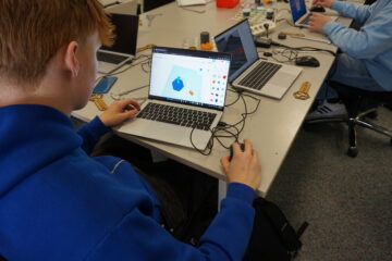
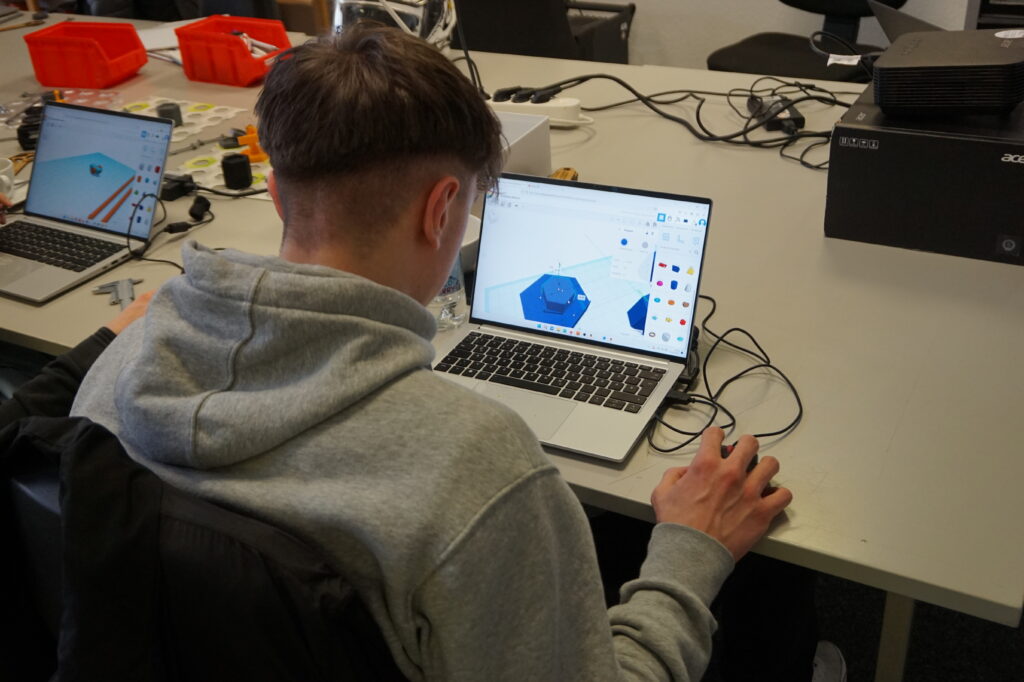
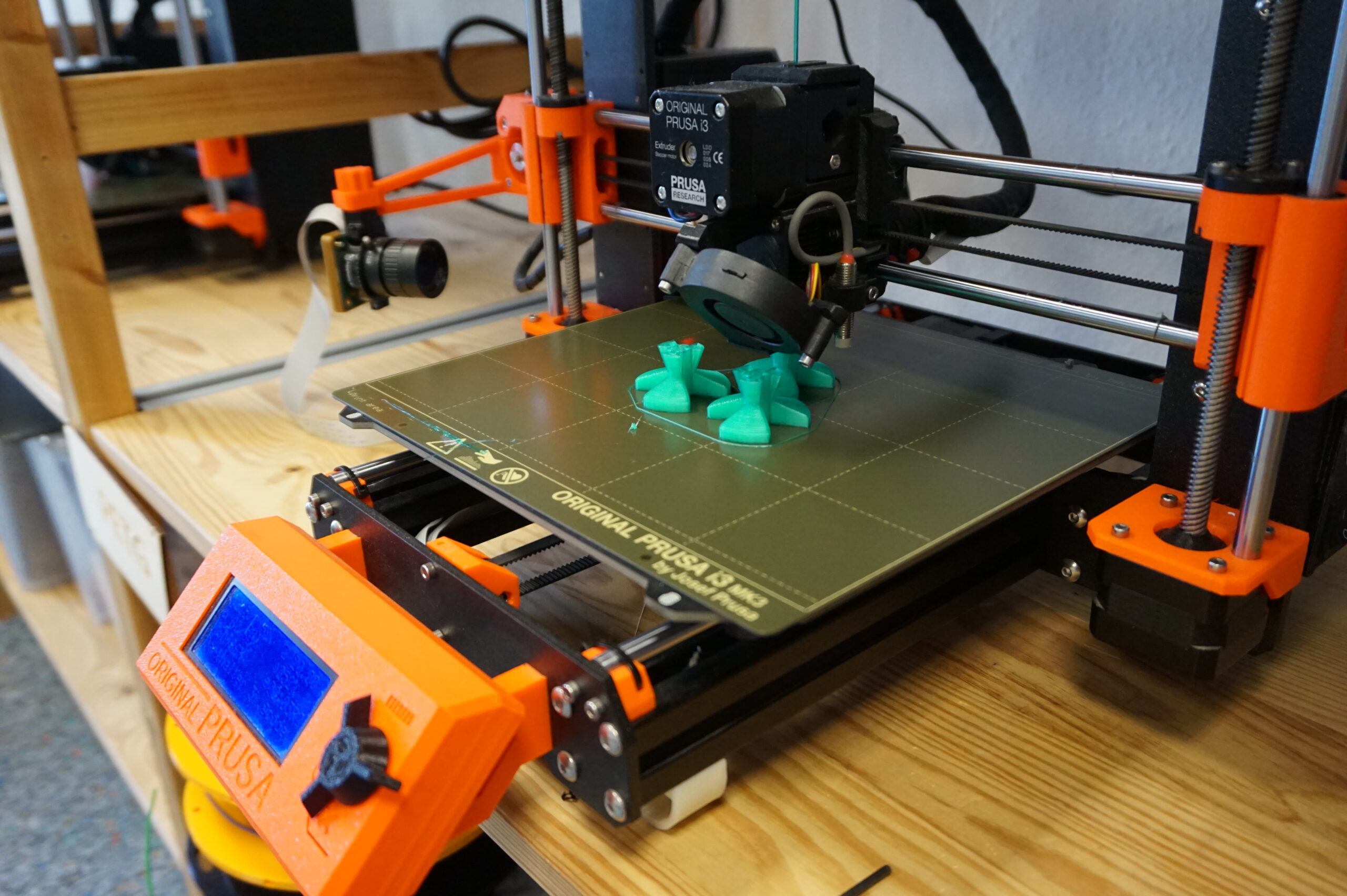
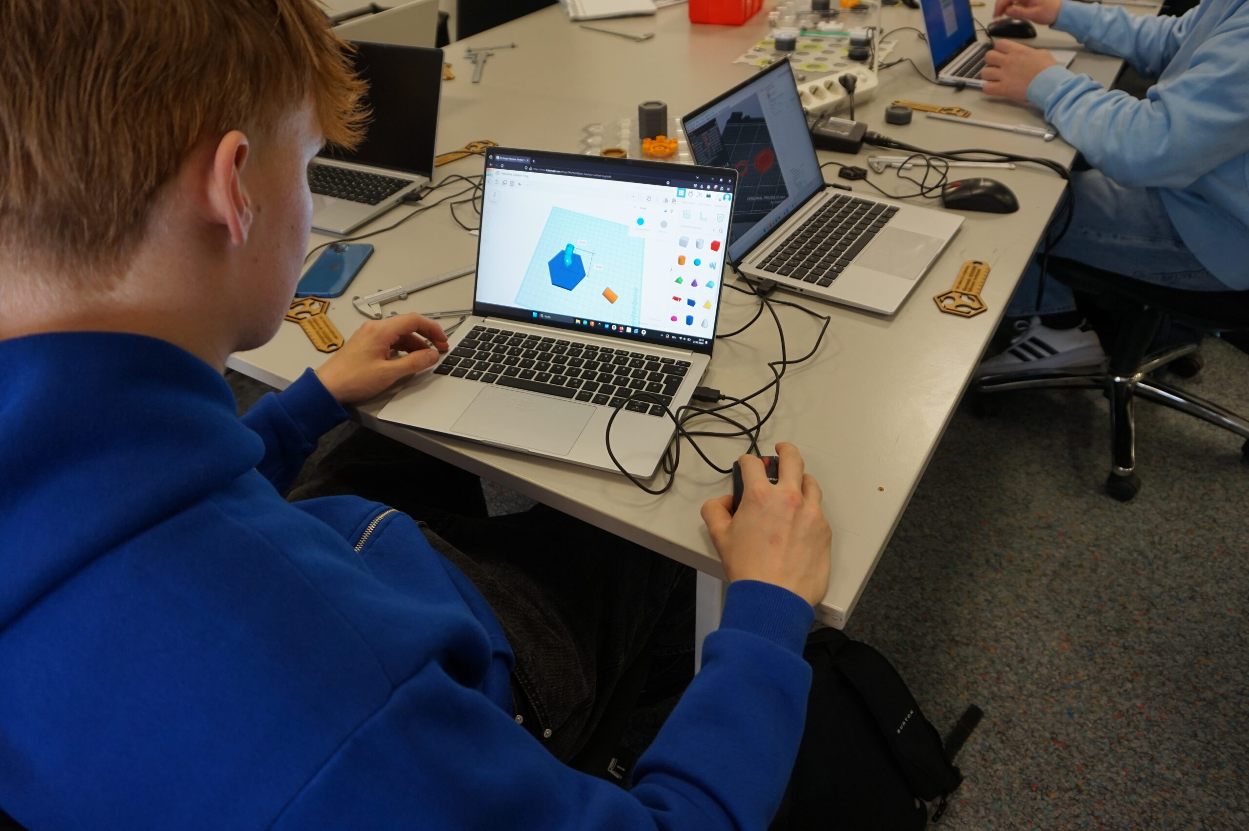
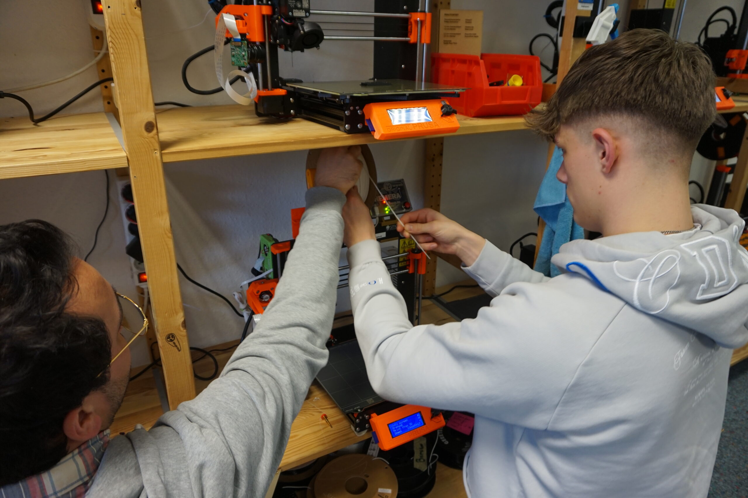
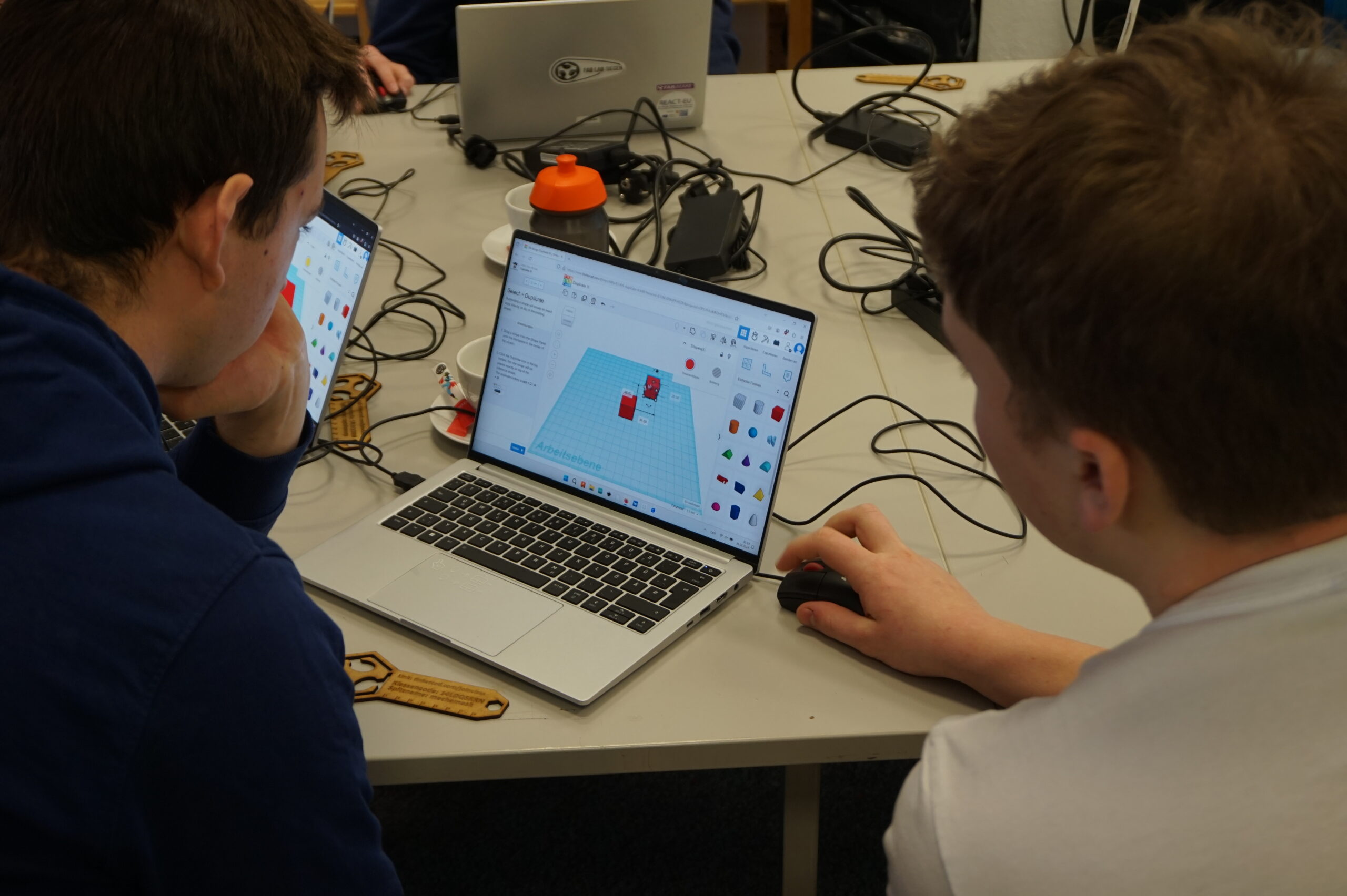
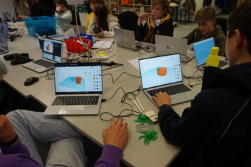
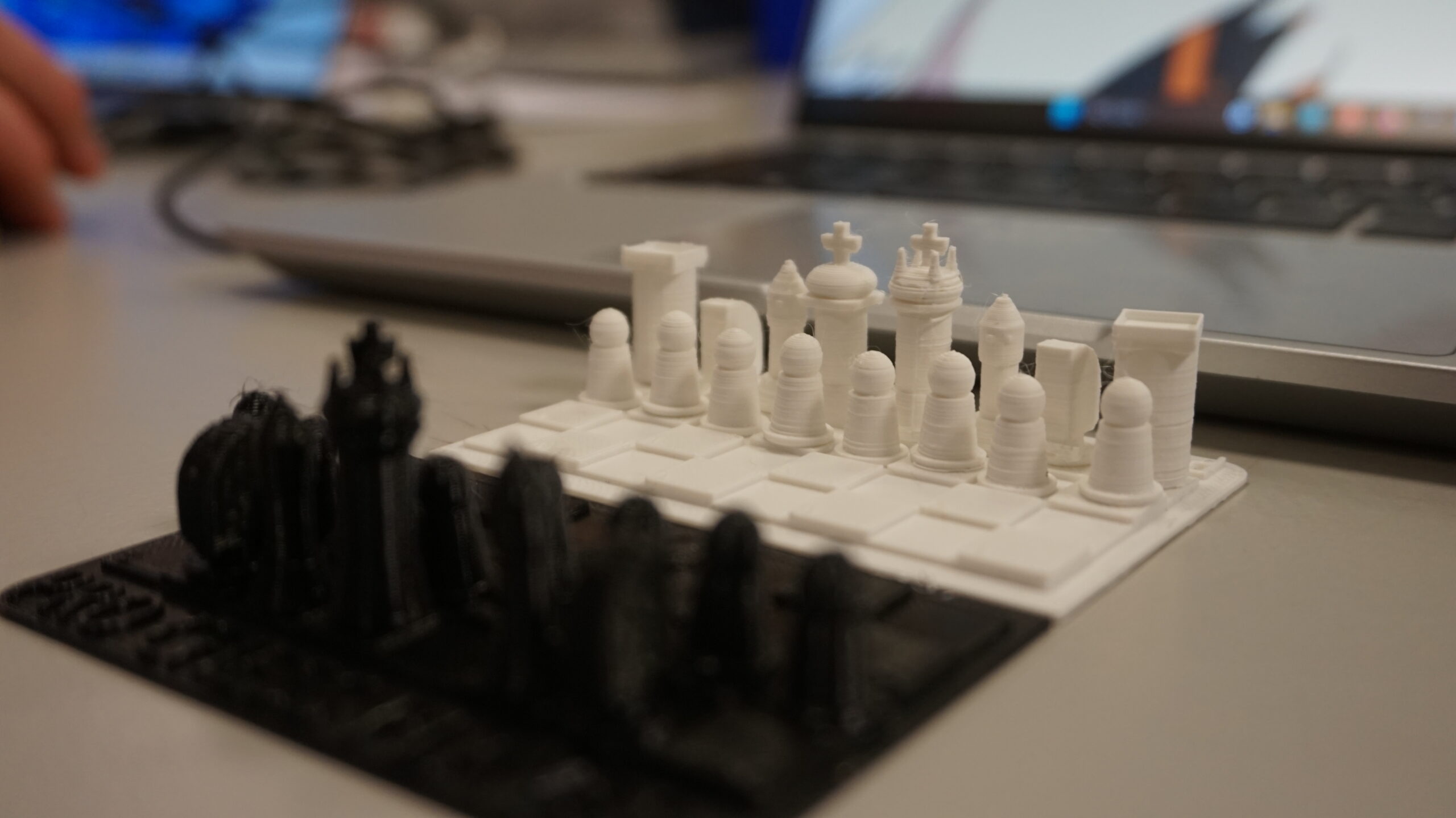
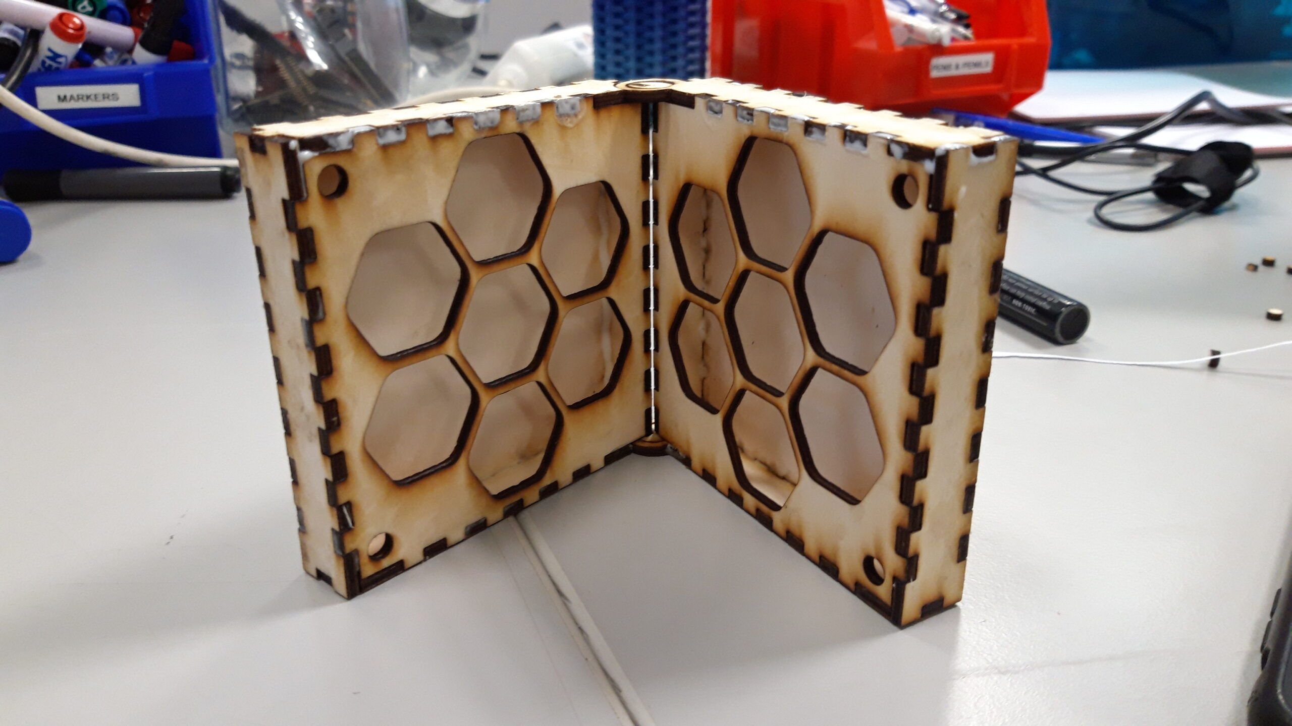
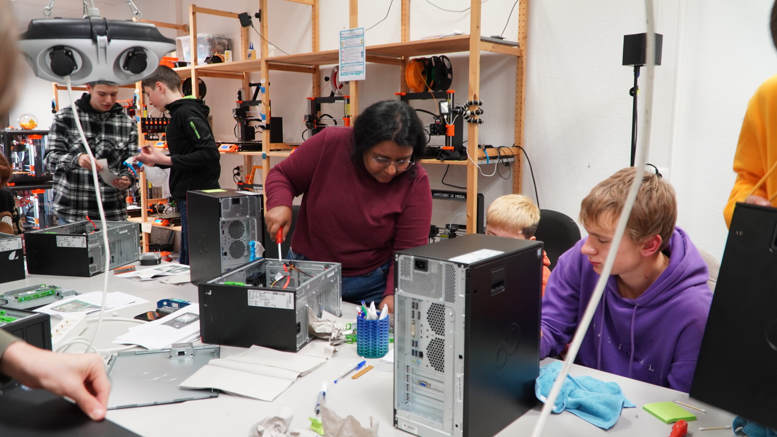
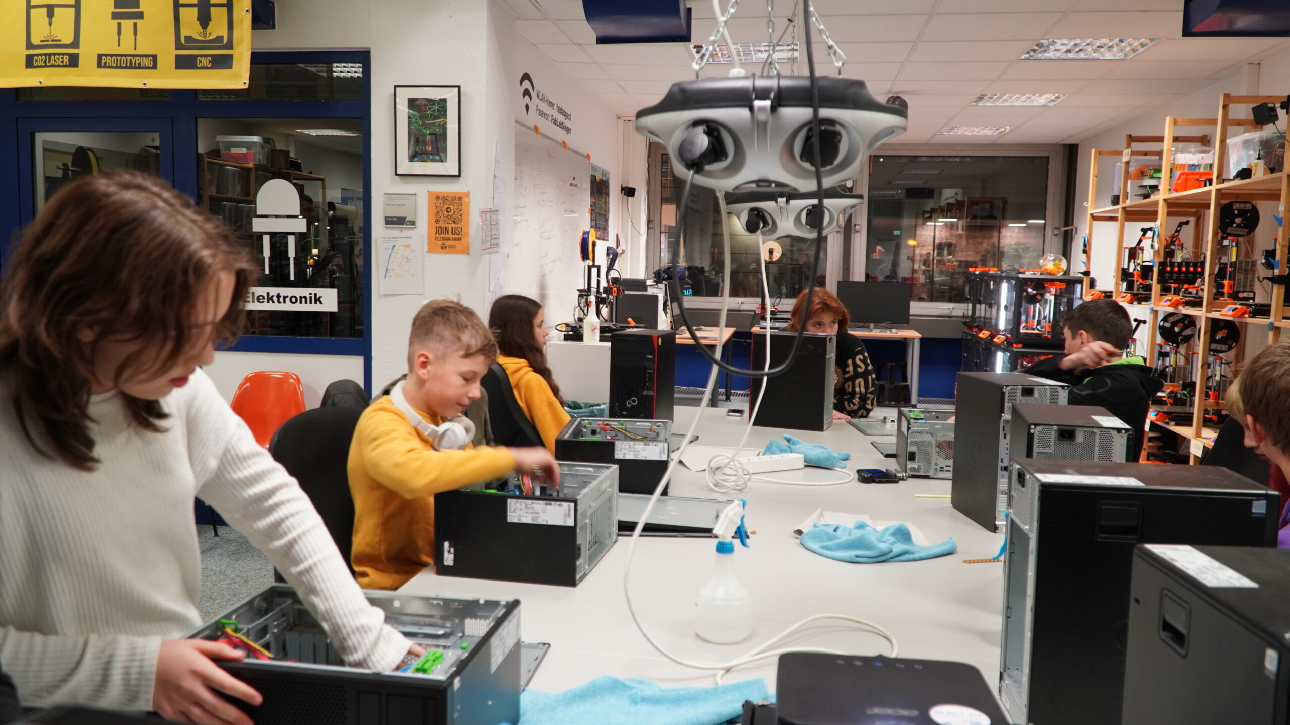
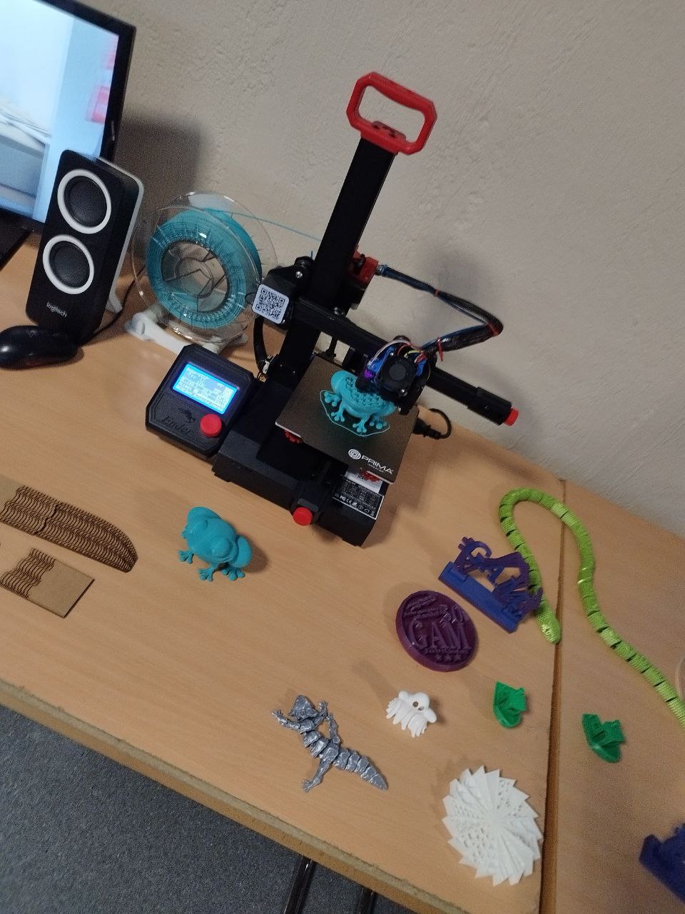
Aged between 12 and 16 years, these young participants already demonstrated impressive technical and creative skills: Over the past five months, ten young participants took part in workshop modules at the Fab Lab. In the end, they presented their projects. The children combined AI-generated stories with 3D-printed models and interactive touch sensors, which they programmed using the Calliope Mini.
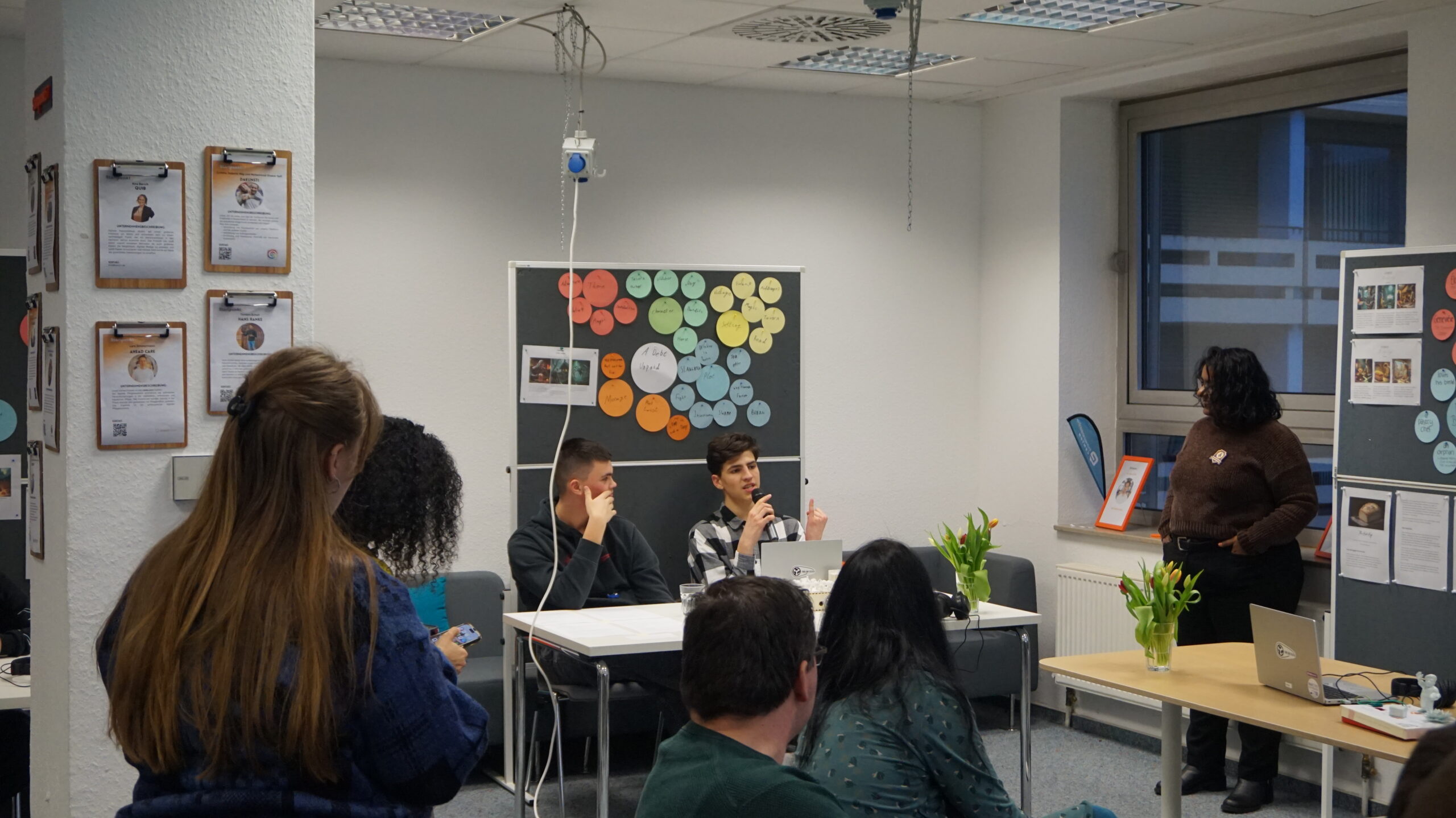
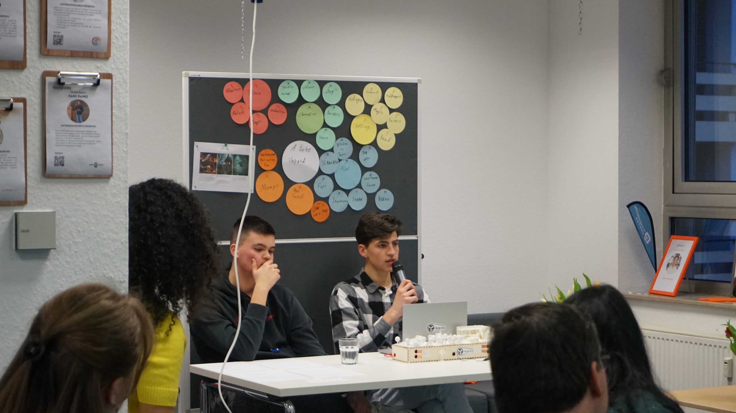
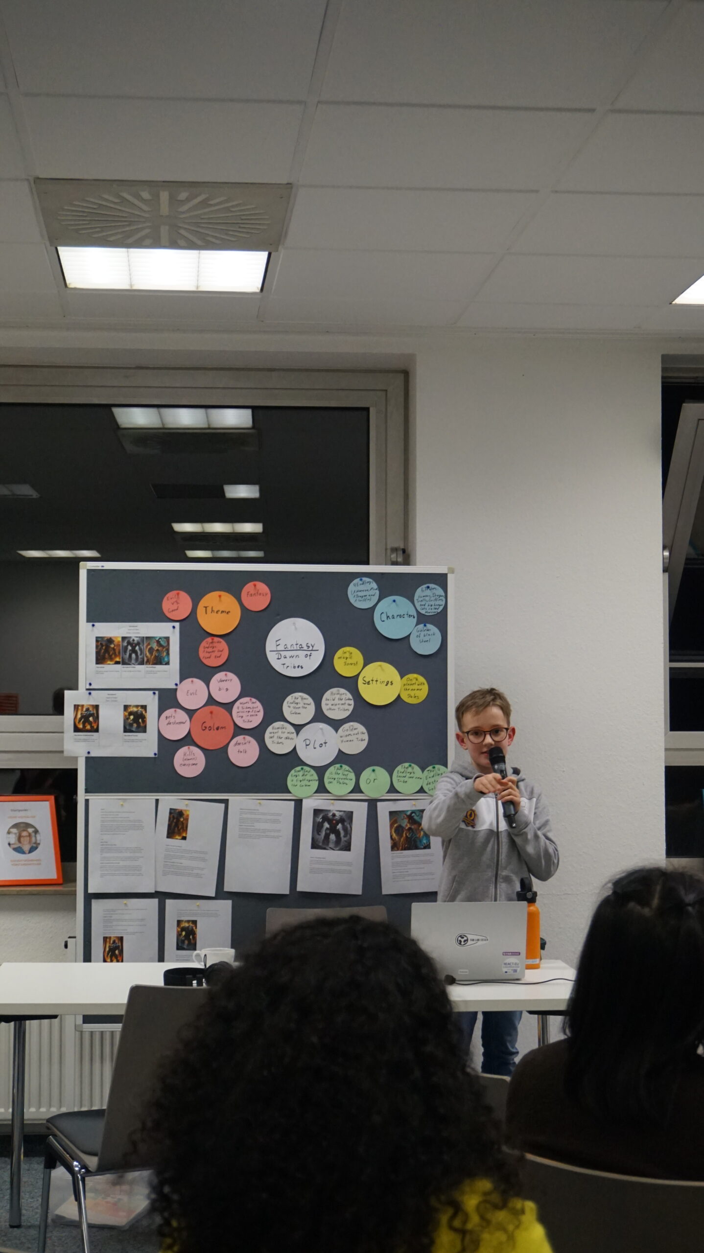
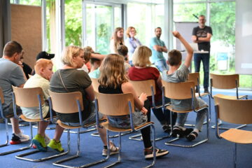
First, each group presented their project in three minutes. Afterwards, the jury and guests had the opportunity to view the projects. The evaluation was based on the following criteria: innovation, creativity and originality, technical implementation, narrative structure, visual/sound design and presentation skills.
The winning projects are:
- 1st place: Dawn of Tribes by Émile Julian Schneider – Prize: Calliope Mini Microcontroller
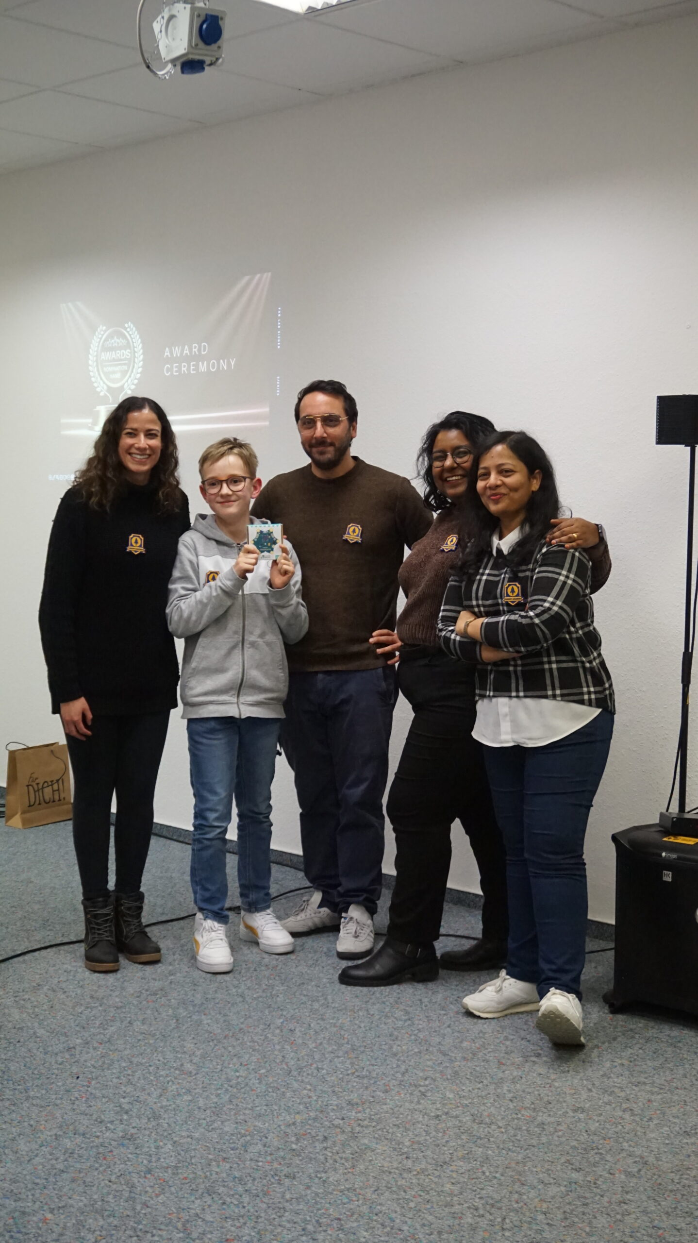
- 2nd place: The Last Loaf by Dorothea Breichler – Prize: PLA filaments for 3D printing
- 3rd place: A Debt Unpaid by David Fedorenko and Vladyslav Halevych – Prize: Arduino Uno Microcontroller
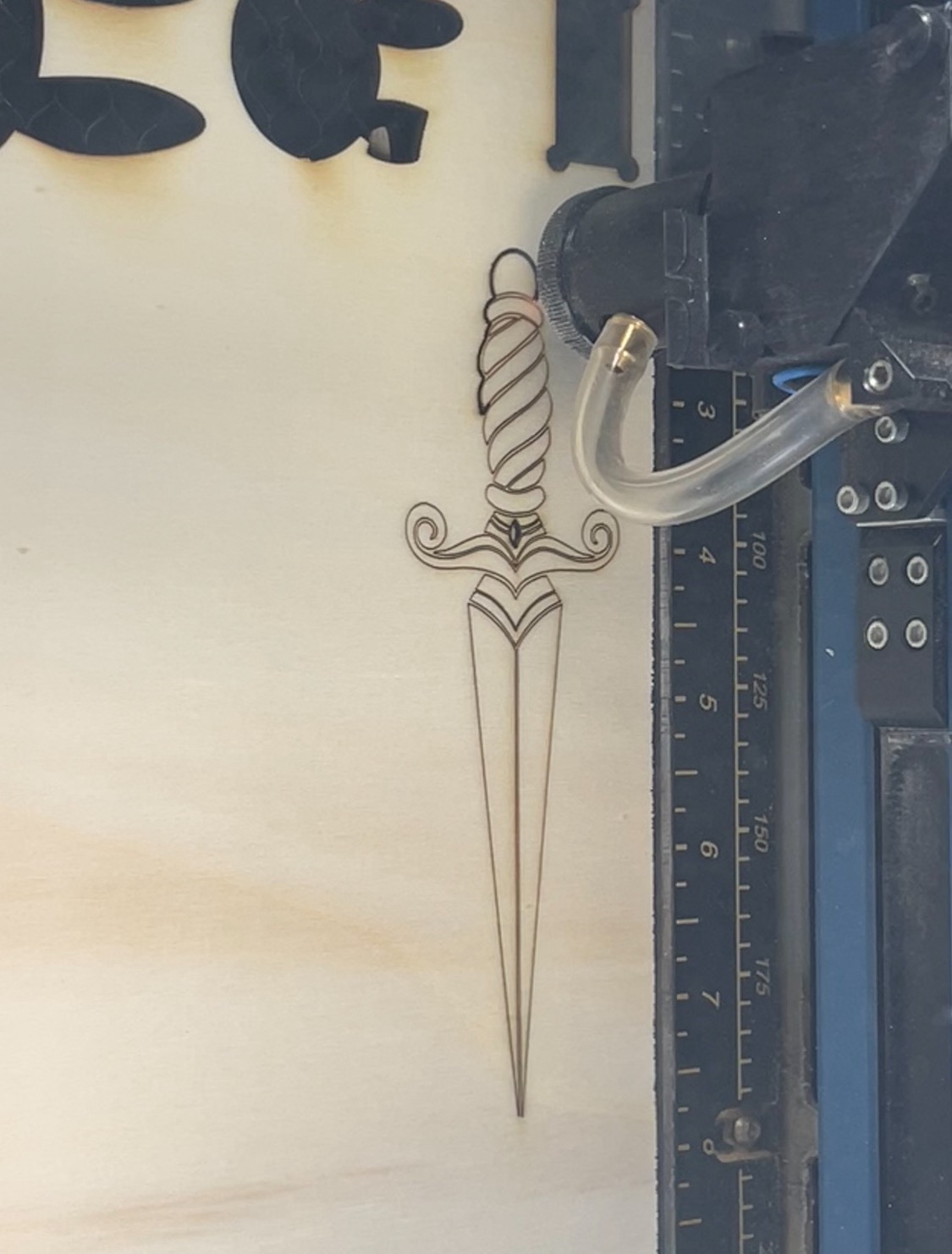
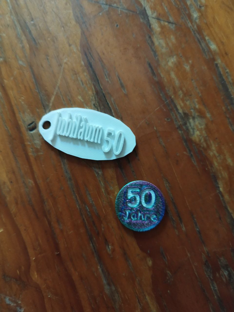
In addition to the main prizes, all participants received a certificate of participation from the University of Siegen and a personalized, laser-engraved badge as recognition of their individual achievements in the various modules.
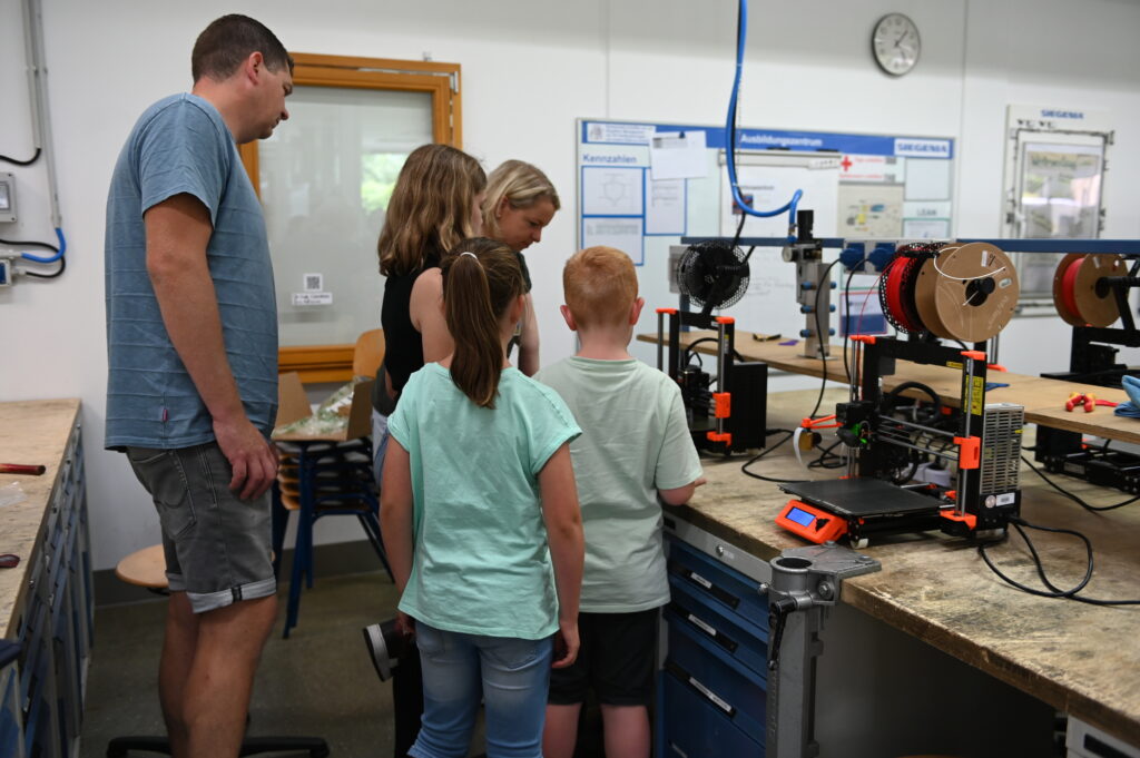
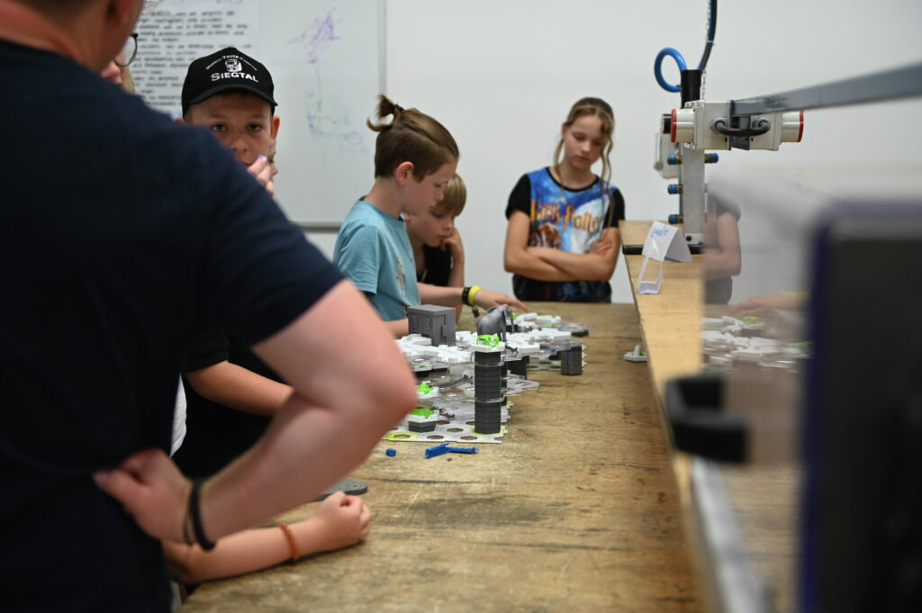
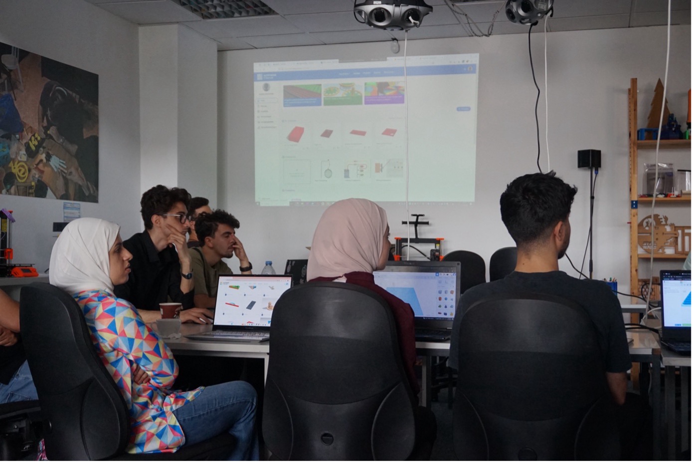
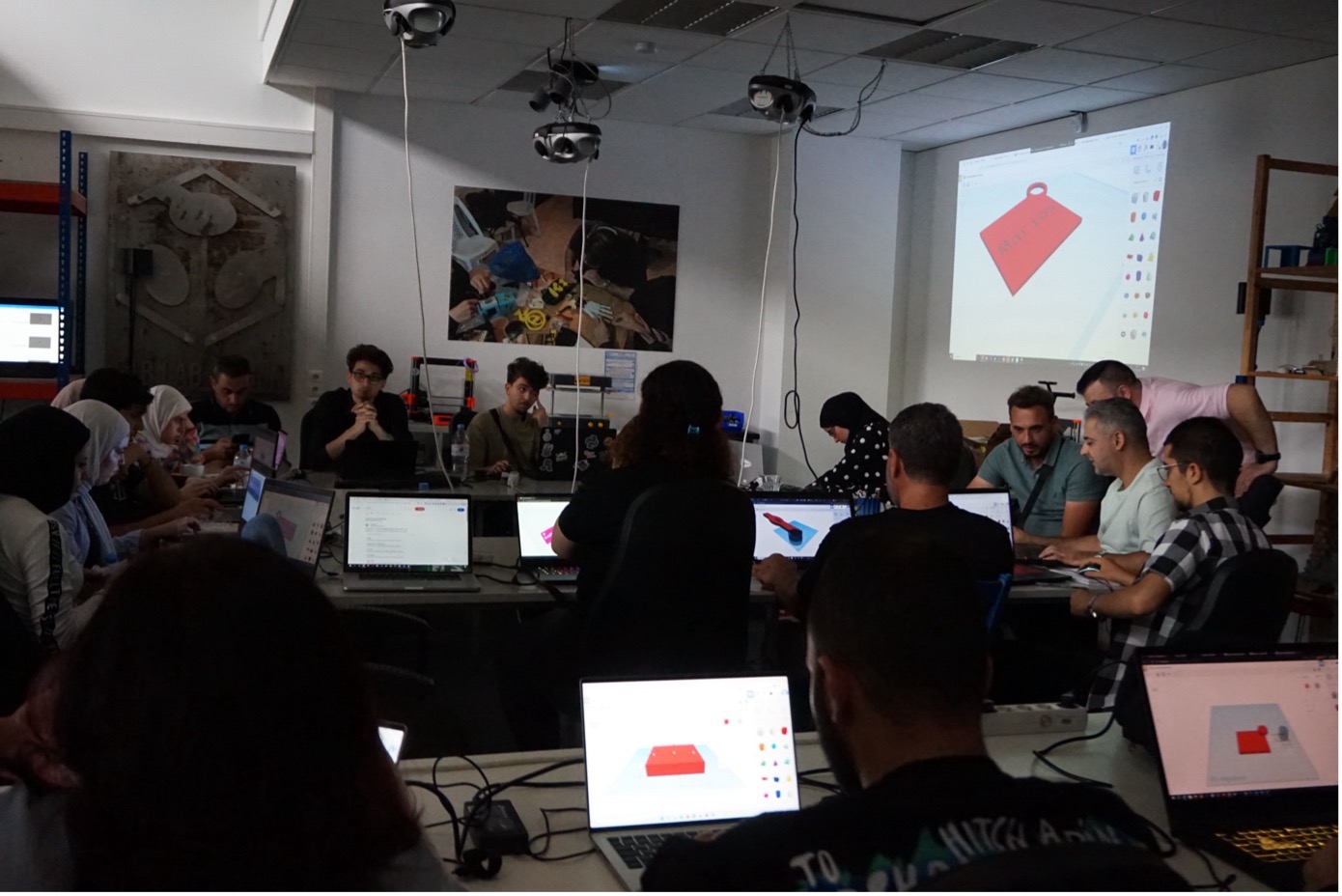
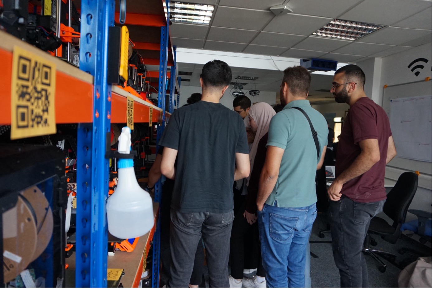
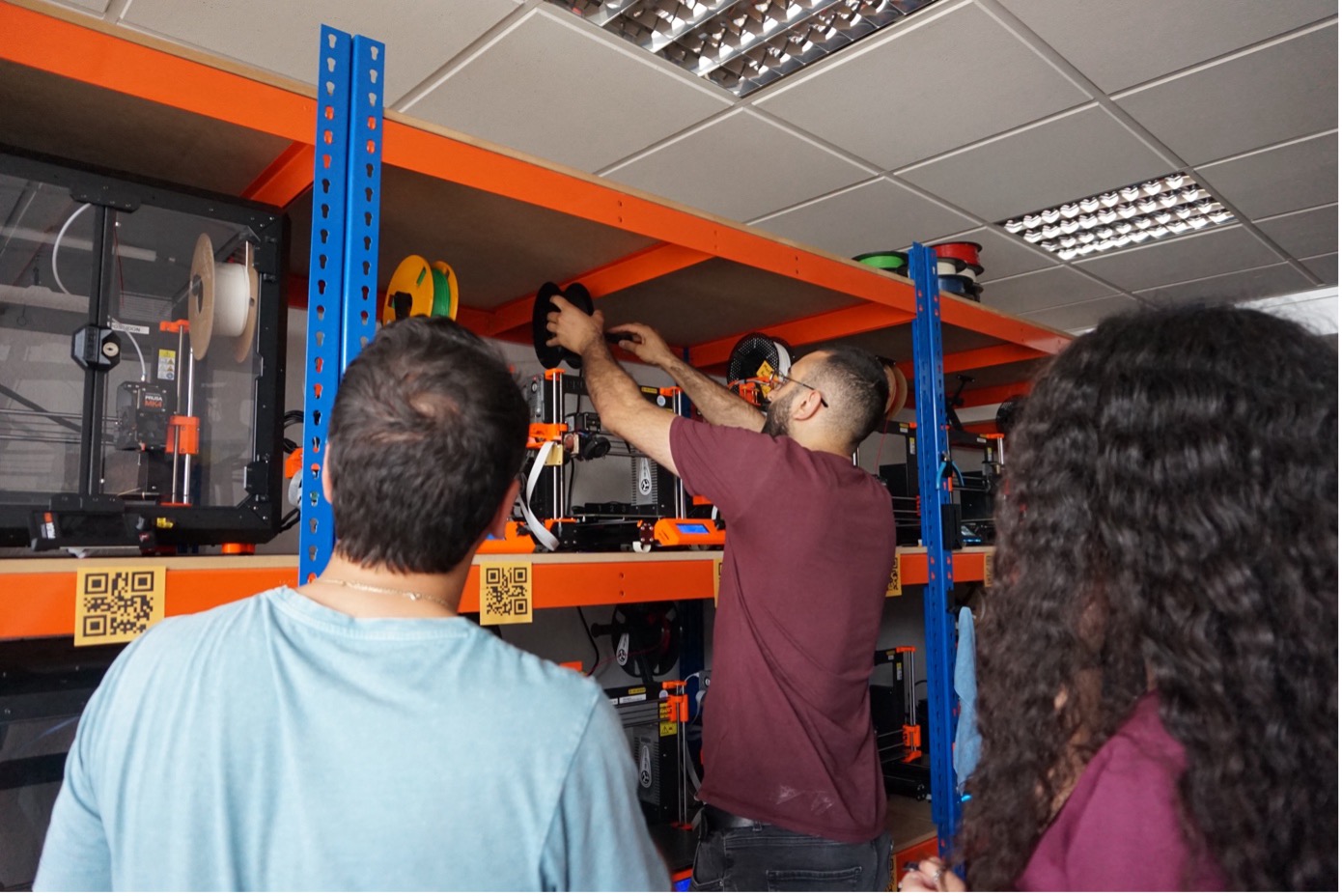
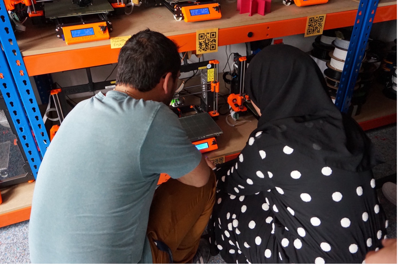
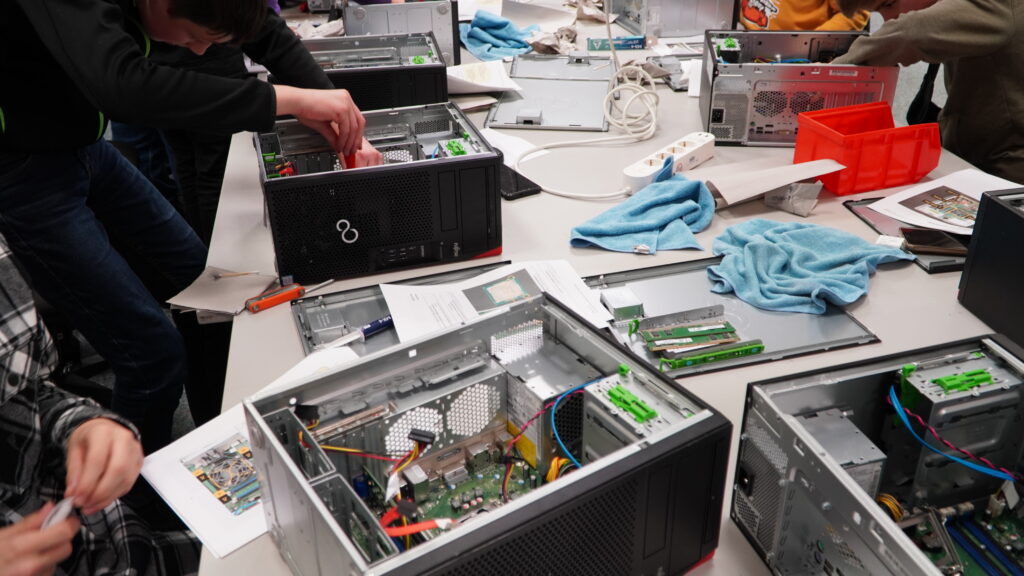
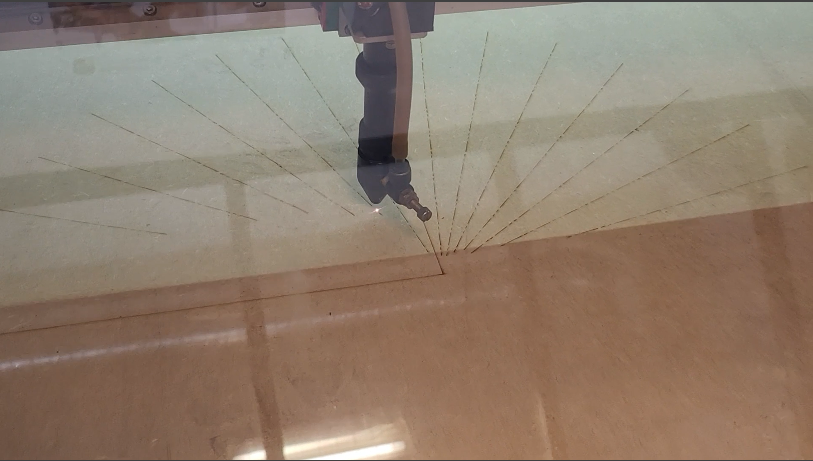
Parents, guests and the jury were impressed by the children’s innovation and dedication. They had participated in five different workshop modules: 3D printing & 3D modeling, Programming with Calliope Mini, Sugar measurement with a photometer, Storytelling with AI, Interactive storytelling.
The Zukunft Akademie is part of the EnvironMINT project, an applied research initiative that focuses on the creative teaching of STEM subjects (Science, Technology, Engineering, and Mathematics) to young people. A key aspect of the project is its participatory approach: Together with young people, parents, teachers, and industry professionals, a concept for extracurricular STEM activities is being developed. The focus is on maker activities, which integrate not only technological but also artistic aspects.
The EnvironMINT project is a research initiative of the University of Siegen and is funded by the German Federal Ministry of Education and Research (BMBF).
The Fab Lab Siegen is led by Prof. Dr. Claudia Müller. The management and project leadership are in the hands of Marios Mouratidis. The scientific staff members Karina Oliveira, Ontika Nazmun, and Hina Firdaus are responsible for the content and operational planning of the Zukunft Akademie.