If you’ve always wondered what a plastic component from a 3D printer can withstand, you’ve come to the right place. As part of the SmaP research project, we teamed up with the UTS Chair of Forming Technology and literally put our prints to the test (yes, well, maybe more like clamped).
The Attempt
The test we have carried out is the tensile test according to DIN EN ISO 527-1. This DIN standard contains the basic information about the exact execution of the tensile test for plastics.

The Sample
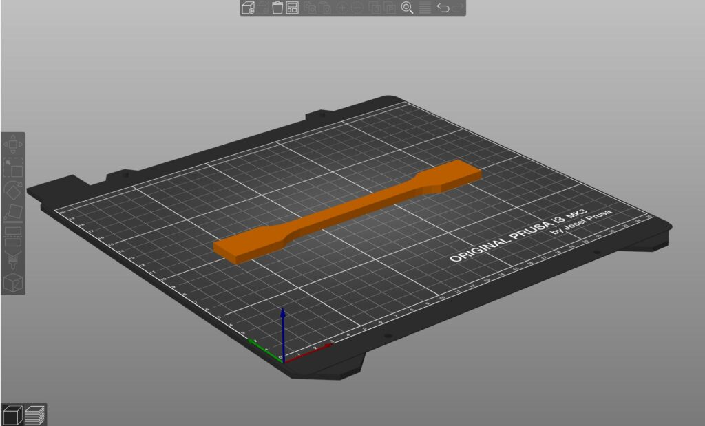
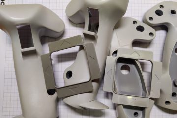
The specimen was dimensioned according to DIN EN ISO 527-2. This standard specifically defines the test conditions for molding and extrusion compounds. In our case, it is an extrusion compound, which is due to the manufacturing process (FDM 3D printers like the ones used extrude liquid plastic into an extrusion compound). Our specimen is a flat specimen of type 1A, this has a rectangular shape with so-called heads for clamping wedges. The width is 10 mm and a thickness of 5 mm.
Test Execution
3 different materials from 2 different printers were tested. 5 samples each were made. Samples of polylactide (PLA) and polyethylene terephthalate (PETG) were printed on one of our Prusa i3 MK3s printers. Furthermore, samples of onyx were produced on the Markforged MarkTwo. Onyx is a nylon with portions of carbon short fibers. For the test, a material sample in standardized form is inserted into a tensile testing machine. This machine stretches the specimen during the test until it breaks or elongation occurs without breakage (looks then like an elongated chewing gum). The specimen is stretched at a standardized speed (1 mm/min). The tensile testing machine continuously pulls the specimen apart during the test. The force that the specimen opposes this imposed strain is meanwhile recorded via the strain. The values in the evaluation can then be determined from the measured data. In the video below, you can see the experimental procedure and the tearing of a sample.
Results
The evaluation contains all essential information about the test and its boundary conditions, as well as a stress-strain diagram, the images of the specimens, and the data on material properties obtained from the test.
PLA

In the stress/strain diagrams of PLA, the range of elastic deformation can be seen in the range of about 0 – 1.8 %, which then stops abruptly when the tensile strength is reached, and changes to plastic deformation. From the area of plastic deformation, approximately between 1.8 and 2%, the quite pronounced part of the necking begins. The material still allows about 1.5% elongation until it finally breaks.
PETG
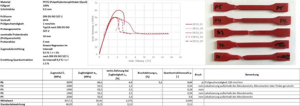
With PETG, the result cannot be reconstructed quite as nicely as with PLA. Sample PETG_P1, the upper outlier in the diagram, changes from the elastic to the plastic range at about 55 MPa, which then leads to necking at 60 MPa and ends in fracture of the sample at an elongation of 5.1%. The four other specimens behave similarly for the most part and also have only a small area of plastic deformation and pronounced area of necking. Compared to PLA, the elastic range of PETG is more pronounced.
Onyx

The onyx material also has a continuous transition from elastic to plastic deformation, although the region of elastic deformation is difficult to discern. Apparently, this ends at about between 8 and 10 MPa and then turns into a very pronounced part of plastic deformation, which subsequently leads to fracture with only slight necking.


Comparison
In this comparison, all evaluated specimens are summarized in a stress-strain diagram.

Here it can be seen that the specimens made of onyx (black) allow almost twice as much strain until fracture occurs, compared to the specimens made of PETG (red). Compared to the other two materials, the samples made of PLA allow even less elongation and are all already torn at an elongation of ε = 3.4 – 3.8 %. The comparison diagram also shows how much stress the materials can withstand, with PLA being the best performer except for the one outlier (PETG_P1). This is followed by PETG and in third place by the onyx material. Comparing all three materials with each other, it can be seen that PLA allows the least elongation in its elastic deformation range, but also quickly leads to breakage of the specimen after exceeding this range. Therefore, it can be said that PLA is certainly the material with the most brittle behavior. If you now want to realize one of your projects, you can follow these results to some extent, at least as far as tension and elongation are concerned, although the three materials naturally have other strengths and weaknesses.