Pre Story
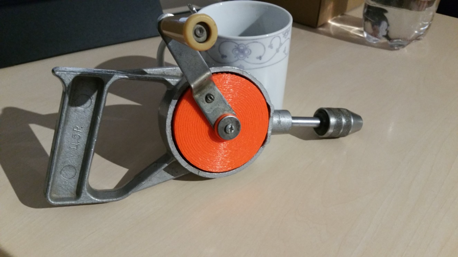
My father bought the thing at the flea market sometime. The price of 5 rubles (Ц. 5Р.) is incorporated in the handle, because at that time in the Soviet Union there was the planned economy and you could get a pack of butter for the same price in the big whole country.
Problem
The drill always did its job. It is particularly suitable for small jobs and you can dose the torque manually. Only at some point the drill got stuck somewhere and my father exerted too much momentum on the big bevel gear until a few plastic teeth sheared off, rendering the thing useless. The old bevel gear consisted of two parts: The front side with the teeth was made of a plastic casting and the back side was made of some kind of metal, which was somehow connected to the plastic (unfortunately no photo). So a new bevel gear was needed.
Solution
First, the teeth of the bevel gear had to be counted. There are 60 teeth. The driven bevel gear has 15 teeth, so there is a ratio of 1:4. In addition, all dimensions, such as the height of the teeth, their width and the bore diameter of the bevel gear had to be measured with a caliper gauge. The problem: the teeth are not simply arranged in a straight line, and their “focal point” is somewhere in the air. They are also wider at the outermost diameter than at the inner diameter of the bevel gear. So the geometry is a real challenge and you can’t just build the thing with a CAD program if you’re not a professional.
But what to do? Fortunately, I happened to come across a solidworks tutorial on the internet. It shows how to create configurable standard parts using the solidworks (SW) design library. And that worked well!
Procedure
Open Solidworks, open any assembly and throw out all the parts. Somehow it didn’t work out any other way for me. Then, on the right side of the screen, open the construction library and shimmy through the tree. Toolbox, ISO, power transmission, gears, degree bevel gear (driving).
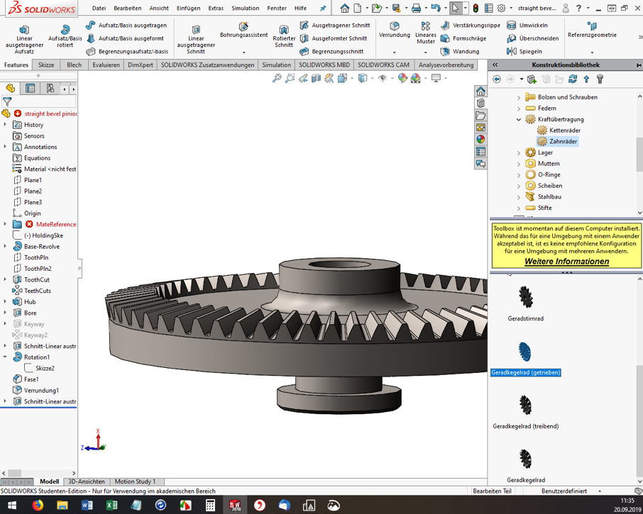
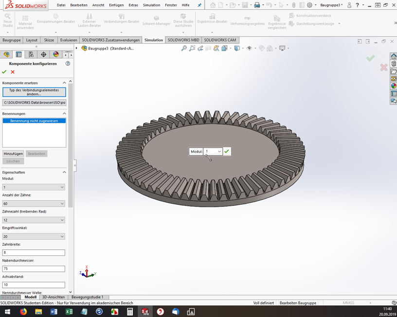
For me, the ISO standard matched well with my Soviet part. Then the “Degree bevel gear (driving)” must be dragged and dropped into the assembly window. Now the “Configure component” dialog opens on the left. The module, the number of teeth, the pressure angle, etc. can be set. Here you have to experiment, have the bevel gear with the green check mark built again and again and measure it. (Tip: If you click on a component edge, the bottom info bar of SW conveniently shows the measured length directly).
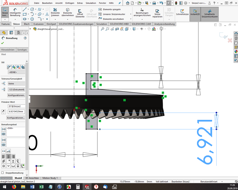
However, you cannot specify all dimensions and geometry properties in the configurator. And here’s where it gets a little tricky. If the tooth geometry of the blank created fits so far, the rest must now be added manually. I used the function “Attachment/Base rotated” to build a created sketch as a body of rotation to the blank (see screenshot). Again, I had to measure the old bevel gear over and over again.
Once you are satisfied with the part, you need to export it to *.STL format for 3D printing. And off we go to the Fab Lab Siegen! Here Fabian helped me out, showed me the 3D printers and started the printing. Thanks a lot! 😊
Result
The first print was unsuccessful (of course). In 3D printing, for example, the holes are always slightly smaller compared to the model. The teeth were also too small, so that they could not engage deeply enough with the opposing teeth. These teeth also sheared off during initial attempts. In addition, the bracket for the crank was a bit too thin and is therefore broken off.

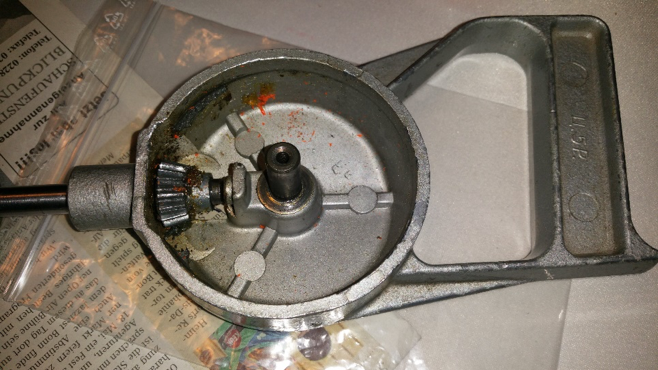
But now it was possible to measure the printed bevel gear and improve the dimensions in SW and finally start a second attempt. However, the second time it went better than expected and the bevel gear installed beautifully. The hand drill runs very smoothly and if any problems should occur in a few years, I’ll just print out the bevel gear again 😉 .
