Soviet hand drill repair

Pre Story

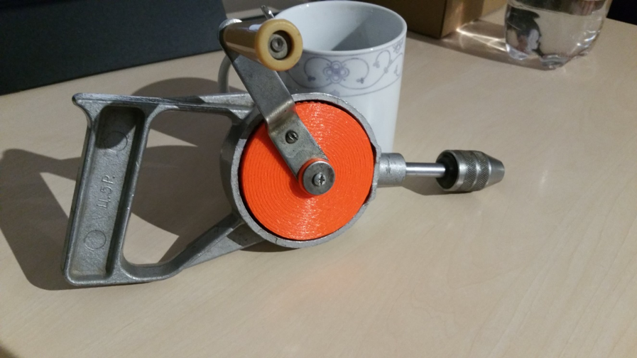
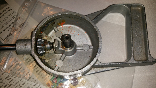
My father bought the thing at the flea market sometime. The price of 5 rubles (Ц. 5Р.) is incorporated in the handle, because at that time in the Soviet Union there was the planned economy and you could get a pack of butter for the same price in the big whole country.

Problem

The drill always did its job. It is particularly suitable for small jobs and you can dose the torque manually. Only at some point the drill got stuck somewhere and my father exerted too much momentum on the big bevel gear until a few plastic teeth sheared off, rendering the thing useless. The old bevel gear consisted of two parts: The front side with the teeth was made of a plastic casting and the back side was made of some kind of metal, which was somehow connected to the plastic (unfortunately no photo). So a new bevel gear was needed.

Solution

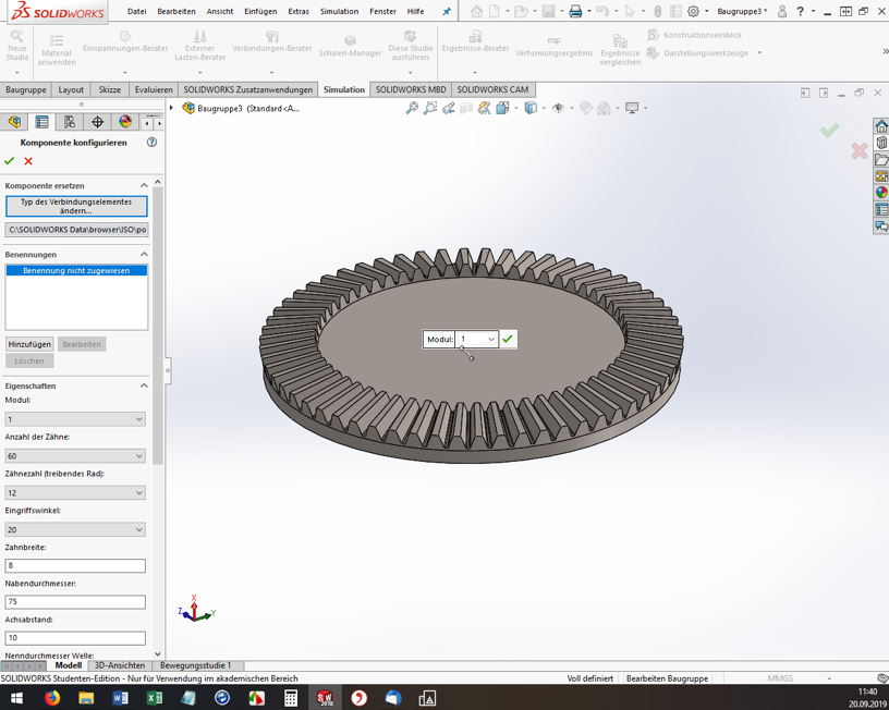
First, the teeth of the bevel gear had to be counted. There are 60 teeth. The driven bevel gear has 15 teeth, so there is a ratio of 1:4. In addition, all dimensions, such as the height of the teeth, their width and the bore diameter of the bevel gear had to be measured with a caliper gauge. The problem: the teeth are not simply arranged in a straight line, and their “focal point” is somewhere in the air. They are also wider at the outermost diameter than at the inner diameter of the bevel gear. So the geometry is a real challenge and you can’t just build the thing with a CAD program if you’re not a professional.
But what to do? Fortunately, I happened to come across a solidworks tutorial on the internet. It shows how to create configurable standard parts using the solidworks (SW) design library. And that worked well!

Procedure

Open Solidworks, open any assembly and throw out all the parts. Somehow it didn’t work out any other way for me. Then, on the right side of the screen, open the construction library and shimmy through the tree. Toolbox, ISO, power transmission, gears, degree bevel gear (driving).

Solidworks

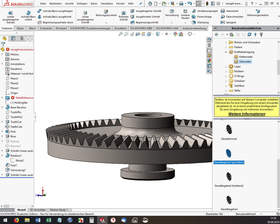
For me, the ISO standard matched well with my Soviet part. Then the “Degree bevel gear (driving)” must be dragged and dropped into the assembly window. Now the “Configure component” dialog opens on the left. The module, the number of teeth, the pressure angle, etc. can be set. Here you have to experiment, have the bevel gear with the green check mark built again and again and measure it. (Tip: If you click on a component edge, the bottom info bar of SW conveniently shows the measured length directly).

SolidWorks-2

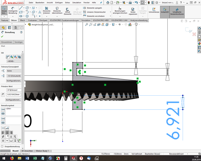
However, you cannot specify all dimensions and geometry properties in the configurator. And here’s where it gets a little tricky. If the tooth geometry of the blank created fits so far, the rest must now be added manually. I used the function “Attachment/Base rotated” to build a created sketch as a body of rotation to the blank (see screenshot). Again, I had to measure the old bevel gear over and over again.

SolidWorks-3

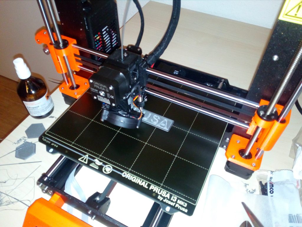
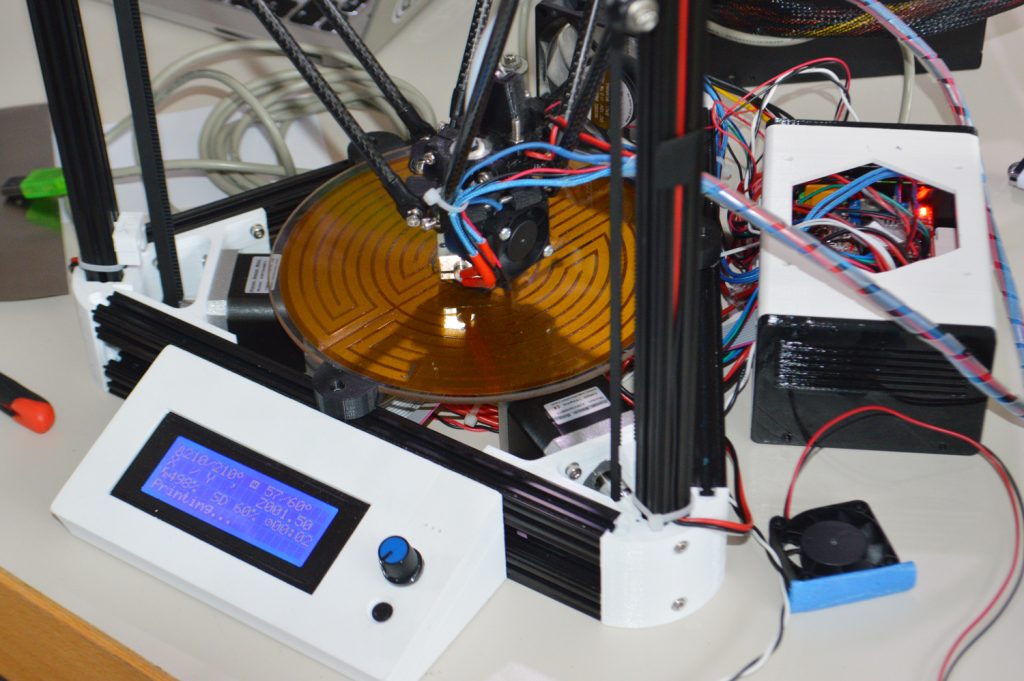
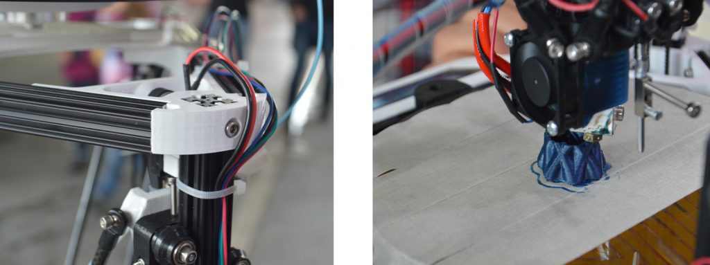
Once you are satisfied with the part, you need to export it to *.STL format for 3D printing. And off we go to the Fab Lab Siegen! Here Fabian helped me out, showed me the 3D printers and started the printing. Thanks a lot! 😊

Result

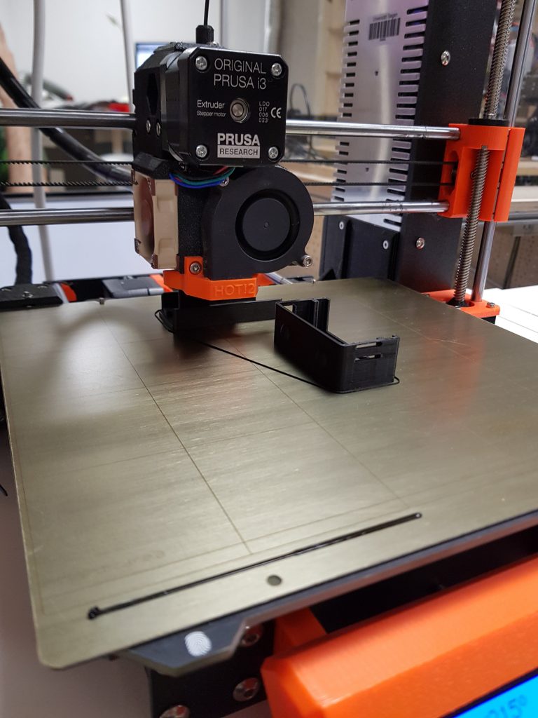
The first print was unsuccessful (of course). In 3D printing, for example, the holes are always slightly smaller compared to the model. The teeth were also too small, so that they could not engage deeply enough with the opposing teeth. These teeth also sheared off during initial attempts. In addition, the bracket for the crank was a bit too thin and is therefore broken off.

Gears printed

Drill machine open

But now it was possible to measure the printed bevel gear and improve the dimensions in SW and finally start a second attempt. However, the second time it went better than expected and the bevel gear installed beautifully. The hand drill runs very smoothly and if any problems should occur in a few years, I’ll just print out the bevel gear again 😉 .

Drill-machine-composed-1

Drill-machine-composed-2

A Child’s Book, or: Saving Plastic, Starting 3D Prints New

During the summer semester 2020, there was a printer in the Fab Lab that was constantly cancelled for testing. The printer with the name “Hades” had to serve as a test object for a children’s book. But what does a children’s book have to do with highly experimental, plastic-saving techniques? Let’s lunge a litte bit.

Earlier this summer semester, I decided to develop a children’s book for 3D printers. Together with my fellow student C. Ajiboye, this became a manual that tells a story on one side, one of Ursa, a girl exploring 3D printing through “Learning By Doing.” On the other side, there were explanations of how Ursa finds problems and what solutions it gives for each of them.
But the last page was special:

A WLAN-enabled (ESP32) microcontroller was embedded in this page. This one could feel touches via its touchpins. I then soldered these pins to copper surfaces and hid them under the page. One laser cut later, the copper surfaces could be seen shining through.

Thanks to these surfaces it was now possible to give commands to the ESP32. And thanks to the Octoprint servers, it was then possible to give commands to the printers. Yes, you read that right, this little book has a remote control for a 3D printer built in.

But What is the Point of All This?

Restarting a 3D print is not an easy task, so far there is not a single Octoprint plugin that dares to do this. The result is that when a print fails, which the sensors do not notice, a lot of time, sometimes days, and also up to kilos of plastic are lost. This book was intended to prevent that.

A book has many advantages: it’s quickly at hand, it’s often where you want it, and the software doesn’t change much. It is also lighter than a laptop and thus handier to use. What’s more, you don’t have to boot it up or preconfigure it. The interface is simply there.

But How do You Restart a Print With a Book Now?

A 3D print is stored in machine code. This “code” is written line by line and executed line by line afterwards. So a group of lines represents a layer, because a 3D print is done layer by layer. If a 3D print fails at one point, the commands could be executed again from this point. In the file, as well as in the real print, an exact height is defined for this. You could measure this height, but neither with the eye nor with a ruler you can find it exactly. With the 3D printer itself, on the other hand, you can find the exact height. Like calibrating old 3D prints, you can now use a piece of paper and the tip to determine to within 0.1mm where a print failed. So, with the book in your hand, you move the nozzle exactly over the pressure, lower it very slowly, and try to feel with a piece of paper placed in between when the nozzle touches the pressure.

The printer then knows exactly where this nozzle is located, if it is still referenced. Based on this height, the code is then split, the necessary initial steps are executed and then the printer prints again as if it had never stopped.

I Want This Too

After this semester I found the time to develop this project as a plugin for Octoprint. So you don’t need your own book and you can try it out in the web interface. But ATTENTION! This plugin is highly experimental and has also once caused damage to a 3D printer. I do not make any guarantees or take any responsibility for future damages and advise to always hover with your hand over the emergency switch until the first layer prints again and you are sure that the printer is working on the correct line.

Yours, Gerrit.

A Suitcase Filled With Heart

At the beginning there is a story. A reappraisal of feeling, put into words and released into the world. “Du dunkles Herz” (“You dark Heart”) by Tobias Gruseck comes as an appealing red booklet and is a story about a suitcase full of money that darkens hearts. But promoting literature depends on more than the content of the text. A myth around it is good, maybe an eccentric author, a scandal. Or a suitcase, in it: hearts. If you touch one of the hearts, or the oak leaf next to it, you suddenly hear voices. Text passages that match the object touched resound softly and wonderfully recited from the case and make you want to listen to the story.

A story is told here with multimedia and attention to detail

Jenny and Simon took on the presentation of the work and built the suitcase. Wired inside is a touch board from Bare Conductive® that is connected via conductive yarn to things that are historically significant and, in some cases, 3D printed. Touching the thread closes the circuit and the text passages stored on the chip and previously recorded with virtuosity are played.

Literature as a haptic experience

All this was first presented in Bad Säckingen at “Kunst trifft Handwerk,” an annual outdoor event at the picturesque Trompeterschlößchen, where Germany and Switzerland bundled streams of tourists before the pandemic moved in. The title of the event also fits perfectly with this haptic project, which combines literary effusion with gifted tinkering. Currently on display at Fab Lab Siegen.

The Pool Bottom Suction Robot Wheel

Anyone who has ever been to an outdoor pool knows how important it is to clean pools thoroughly. In the past, people might have been sent down there with a rag, but nowadays this is done by pelvic floor vacuums, small waterproof robots made of plastic and electronics that move back and forth tirelessly on the floor after closing time. The open-air swimming pool in Kaan-Marienborn has just such a machine, and one of its wheels was broken.

Lab manager Marios, Ms. Königsberg and Mr. Wagner from the city of Siegen, mayor Steffen Mues, operations manager Dirk Räwel and Jonas from Fab Lab, who built the wheel. Picture: City of Siegen

So we received an inquiry from the city’s sports and pools department asking if we could print something. The original manufacturer was no longer available and a new device would probably have blown the already tight corona budget. So Jonas and Marios took care of rebuilding the old wheel, first digitally and then printing it out in durable ABS. The mayor was also there and saw for himself that everything works – the application possibilities of Fab Lab Siegen are well received. So now spare wheels are no longer a problem and the robot is looking so confidently ahead, it has even taken on a part-time job at the indoor swimming pool at Löhrtor!

Press echo

10.07.2020 – wirSiegen
Outdoor pools: replacement wheel for pool cleaner comes from 3D printer

13.07.2020 – Westfälische Rundschau
Siegen: Wheel for outdoor pool vacuum cleaner from 3D printer

Face Visors Against The Virus

After the closure is before the start of production. After all, we, like many other public institutions, had to cease our operations on March 16. Now there were a dozen 3D printers standing around unused. MakerVsVirus and other ideas and projects that developed online in the following days invited us to do something against the virus.

Well, to make a long story short, we are now producing facial visors to reduce the risk of infection to medical personnel and other at-risk groups(the hip girls and guys also call them covid shields). The visors are given free of charge to medical facilities.

Our dear colleagues from the press office have also enriched the whole story with a little more detail and written it down here: Fab Lab of the University of Siegen prints face visors.

What Can I Do?

We can use donations of materials and assistance in making them!

Concrete we are searching for:

  • PETG-Filament 1,75mm
  • PETG-plates 0.5mm, transparent and clear
  • Elastic head hole rubber bands
  • Companies and individuals who have free 3D printing capacity themselves

Feel free to contact Peter Kubior:

Help, I Am a Medical Facility and I Need Visors!

Medical facilities interested in the facial visors can contact Peter Kubior by email:

I Am from The Press and Want to Know More!

Please contact our press office directly for further questions.

Stay healthy. #physicaldistancing not #socialdistancing
Your Lab-Team!

Pressreview

Not Bad for Friday The Thirteenth

A contribution by Ingo Schultze-Schnabel

On the evening of that December day in 2019, I held in my hand the first copy of a 3D print of one of my designs.

Finished print still on the 3D printer

I have been working artistically with multipart images and objects since the 90s and was looking for a method to transform a design into a sculptural object from the 3D printer.

Members of Fab Lab Siegen accompanied me in several steps: From the basic information about the Fab Lab and its possibilities, the ways of designing from “my” graphics programme via CAD programmes to the printer control, a lot was new for me. But in the great working atmosphere it was fun to get involved with new things.

Now the new object hangs provisionally on the wall, for “test viewing”, so to speak. I am concerned with the mechanisms by which our perception “sees” something as a whole with the help of partial information. The quality of visual information, redundancy, the “information gap” – such terms run through my head.

3D print hung on the wall

Here in the work you can see how, despite the distances between the stripes, the impression quickly arises in many places that rectangles, seen in perspective, are being depicted there. The gap suddenly becomes information. With David Amend at the end of the day, I got to talk about how the exact same thing is happening with fake news, an area in which he had experience from a computer science perspective. This is how fragments become a narrative and how easily “truth” emerges in our minds. That brings me back to my artistic theme.

If you want to go a little deeper, you can find more material on my blog.

If you want to experience more art in Siegen, please refer to the ChaosFlux from 24-26 April. Mehr Infos: https://chaosflux.de/de/about/

The Creation of a Bow Handle

A contribution by Philipp Dasbach

The Problem

In archery, the repeatability of the entire shooting process is
crucial for a good result. I myself have owned an Olympic recurve bow with sights (aiming device) and stabilization system (weights for balancing, for smoother aiming) for several years.

Characteristic of this type of bow are the curved or backward bent ends of the bow, from where the English term “recurve” comes.
Unlike other shooting sports, where, for example, is shot over the rear sight and front sight, the sight of the recurve bow has only the front sight. Thus, the body posture and the stopping point of the bow (anchor point) form the second reference point of the recurve bow to define the direction in which the arrow flies. That is, even if the front sight always points to the gold (center of the target), but the bow is slightly different in your hand than it was when you shot it before, the arrow will hit somewhere else.

Therefore, many archers customize the grip of their bow with grip tape or modeling clay to craft a grip that is perfect and stable in their own hand. Since I was not satisfied with the grip of my bow, I decided to design my own grip, which also looks professional due to 3D printing.

The Recurve Bow

Attempts to apply known knowledge

Before I designed the grip according to my ideas, I first wanted to copy the original grip of my bow, so that I could make the adjustments that seemed reasonable from this basis.

Due to my mechanical engineering studies at the University of Siegen, I am familiar with the use of CAD software and have confidently approached the design. However, two things caused me an unexpected amount of problems.

First, it took me a long time to design the many interlocking fillets of the handle. These fillets are very difficult to reproduce with software solutions from the mechanical engineering sector, since they usually have defined geometries. This took me some time, but also forced me to learn new features and capabilities of CAD software.

The second issue that cost me a few tries in 3D printing is the measurability of the hard-to-define geometries.
Since the handle has only a very narrow, straight edge, it was very difficult to measure the position of the hole, bevels and radii. However, it is important for the attachment of the grip piece to the sheet that the geometry of the grip piece corresponds exactly to the geometry of the receptacle provided for it on the sheet. Since I could only roughly estimate many dimensions, I had to approach the correct geometry step by step through trial and error.

During this trial and error, I was able to learn a lot about 3D printing from the staff and makers in the Fab Lab. Above all, they helped me find the ideal slicer settings for my part and the right material. In addition, the Fab Lab works with different CAD programs, all of which have their strengths for different problems.

Prototyping

After four attempts I had copied the original grip of my bow sufficiently well and started with attempts to adapt the grip geometry to my hand. In the process, I tried a total of five different versions.

First, I made changes that seemed logical to myself to stabilize certain areas of the hand to prevent it from slipping back and forth. On the other hand, I combined this with geometries of grips from different manufacturers to arrive at my individual and optimal grip.

Currently, I have mounted a version of the grip on my bow, in which I have rounded some disturbing edges of the original grip and minimize the back-and-forth slipping by changing the angle of the contact surface.

Arch with mounted handle on bracket

Satisfied, but surely there’s more?!

I definitely achieved my goal of getting a better grip than the old one. Whether I have already found the ideal solution, I do not know, because there are still some geometries that I could try.

In the meantime, I uploaded the latest version of the grip to Thingiverse and hope to run into an archer who also uses my grip. Overall, I have to say that through the exchange in the Fab Lab I got ideas and tips that I would never have come up with on my own.

Handle piece, mounted on bow

Copyright Pictures: Philipp Dasbach

Creation of a Tabletop Game

A field report by Tim Dümpelmann

When I entered the Fab Lab for the first time in November, I was really amazed that there was such a great place here in Siegen. The people were very nice and open-minded and I felt comfortable right away. I guess it’s also because I’ve always been a bit of a technology nerd.

An Idea is Quickly Found

The 3D printers have aroused special interest in me. Not only because it was exciting to watch them work, but also because I am somewhat involved in 3D modeling as a hobby. Over the next few weeks, I was at Open Lab every Friday. There I met many nice, interesting people who were all working on great projects.

I think creativity is somewhat contagious. Therefore, it did not take long and I had also decided on my first project:
i wanted to create a tabletop game, model all the game pieces myself and make them with a 3d printer.
Since I had just rendered a great picture (see below) of a “MechMiner” for a science fiction contest, I took it directly as a template for my first figure, the “resource collector”.
mechminer-modell
minersmall

The Right Manufacturing Process

Then I just started modeling. In doing so, I often reached the limits of the FDM printing process due to the small dimensions of my figures and the many details in the 3D models. Therefore, I considered a modular plug-in system to be able to print as efficiently and detailed as possible. I was offered to use an SLA printer, which has much higher precision, but dealing with resins and other liquids is not really my thing.

IMG_20190329_223633_426
IMG_20190329_223626_578

Build, Build, Build

With most problems, both in modeling and in manufacturing, someone was always ready to help me. Since the laser was a little more complicated to use than the 3D printers, I was also quite happy about it.
Since the laser was a little more complicated to use than the 3D printers, I was also quite happy about it. This one was perfect for making a nice modular game board. At the moment the game is not finished yet, so here you can see only a prototype for testing the game mechanics.

IMG_20190317_003814
IMG_20190329_223410

It will be some time before the first version can be played. Balancing will take a long time, and there are still many game cards to be designed.
I have already put the 3D models into a Github project. Stay tuned!

And Around It: The Lab

I myself could also help some people with their projects with my knowledge, and it makes me a bit proud :). I think coming together and working with like-minded people is what makes Fab Lab such a great place.
The technical competence of the staff is high and they do their work very professionally.
The Lab provides opportunities for everyone to try out technology. And I definitely found some people there that I would call friends.
In the meantime, I own my own 3D printer to move the project forward.
Thanks again to everyone who helped set up and troubleshoot!

IMG_20190316_193046

In my opinion, a place like the Fab Lab is an enrichment for Siegen. I just don’t understand why so many people walk past it. 😮 Anyway, I’m looking forward to spending more time there.

Until then: Happy work!

A Raspberry Pi Case Rarely Comes Alone

A field report by Henning Schroeder

In mid-January 2019, during the course of a project with my Raspberry Pi (Wikipedia) 3B+, I was looking for a suitable case that would hold my PI with a 3.5-inch TFT screen. Since I’m new to Raspberry Pis, I thought that doing as much as possible myself would get me up to speed faster than click and buy products from various online markets. With this in mind, I searched for a company in Siegen that performs 3D printing. Right on the first Google run, I came across the Fab Lab website. After a quick phone call to the Fab Lab, I got the info to just come by the following Friday. So it happened that shortly after I entered the Fab Lab I was shown the entire Fab Lab, the staff and the equipment in an extremely friendly manner. The concept of the Fab Lab was previously only known to me from articles on the web. However, this still seemed a long way off for a city like Siegen. All the more I was surprised and thrilled. Everyone present made a very nice impression while focused but always helpful in the Fab Lab.

The 3D Model and Printing

So, with the help of Fabian, I started using the Slice program (Wikipedia) to prepare the file I had previously downloaded via Thingiverse for the 3D printer, brand “Prusa“. After slicing, we exported the generated G-code (Wikipedia) to an SD card, again plugged it into the 3D printer, and started preparing it at the printer. This consisted of removing any previous printing residue from the printing plate with an alcohol solution and then briefly polishing it. After that, we started printing with a few keystrokes. According to the ad, this was supposed to last longer than the Fab Lab’s opening hours, whereupon Fabian made me the offer to put the print on a shelf after it was finished, from which I could pick it up at any time. After a few more Q&A situations that I needed to understand the complexity of the community/open source model in Fab Lab, I left.
Print of the Raspberry-Pi housing

Mistakes Lead to New Ideas

Of course, only to return to the Fab Lab three days later in the evening, full of excitement.
I tried to insert the PI including the screen into the case directly after I had fetched the case from the aforementioned shelf. Unfortunately, the top layer of the screen cracked in the process. This can probably be attributed to the ambient temperature at that time, which is probably not very good for a screen at 0°C. Mistakes in a project and frustration lead to new ideas (at least for me).

A Project Rarely Comes Alone

So it came that I was looking for a new housing project. This I started slightly smaller and simpler than the screen case. Again on Thingiverse. Once again soaking up ideas. Using software called Blender (Wikipedia), I created a “thrifty” cage-look bumper case over many hours of gruesome desperation. The next Friday, for the next Open Lab, I sought out the Lab again to dive into 3D printing. After a little help from the Lab visitors and staff present, the bumper case printing began. This one also worked to complete satisfaction and fits spot on.

Now I am busy with my thoughts around the next project at Fab Lab Siegen.

3D Models to Copy and Develop

The 3D models for the Pi cases are also available for download:

Aya – a Selfmade 3D Printer

Aya – that’s a 3D printer that students of the Human-Computer Interaction master’s program produced in the winter semester 2015/2016 as part of the “3D Printing” seminar.

At the beginning of the seminar, the students were first familiarized with the basics of digital fabrication: What manufacturing processes are there, what materials can be used for printing, what are the possible application potentials? They also learned more about the individual steps of 3D printing: from modeling, to slicing (the “translation” of a 3D model into instructions for the printer), to the printing itself. For the subsequent project work, four students decided to devote themselves to building their own 3D printer.

The project participants used a kit as a basis, which already contained most of the parts needed for construction. All blueprints as well as the control software are available open source and so the students first built the printer according to the distributor’s template. However, they quickly discovered that not everything was working properly. So they decided to print some housing parts themselves using a different 3D printer in the Fab Lab and made other changes to improve print quality, such as adjusting the holder for the consumable. This was followed by a longer calibration phase, because the automatic support systems, which the printer actually has for this, unfortunately didn’t work quite as well as expected.

The students spent an entire semester working on the printer, which they named Aya (after a Japanese movie character). Aya is a Delta Robot 3D printer whose distinctive feature is its design: The three-axis system, which differs from conventional printers with linear axis systems, enables fast, precise printing. In addition to smaller test prints, the first larger prints such as an owl or a vase have already been made. Initial test runs indicate that Aya can print at a fabulous speed of up to 300-350 mm/second.

Even though the study project has now been completed, the students want to continue working on optimizing the 3D printer. For example, the installation of the control electronics or the stabilization of the base frame is being considered here to make Aya more transportable. There are also plans to test Aya with other materials such as ABS – the plastic used to make Lego bricks, for example – because so far only PLA, an environmentally friendly plastic based on (corn) starch, has been used as a material.

The students themselves learned a lot about 3D printing during the seminar and by building Aya. On Technology Day, the printer was presented and used for the first time in front of a broad public.

Aya in full size: