Zusätzlich zu unseren Open Lab Zeiten jeden Mittwoch von 14 bis 20 Uhr gibt es dieses Sommersemester auch Zeiten, an denen das Lab extra für Studierende geöffnet ist. Studierende können ab sofort auch an Dienstag und Donnerstag zu folgenden Zeiten im Fab Lab arbeiten:
Dienstags von 13 – 16 Uhr
Donnerstags von 14 – 17 Uhr
Diese erweiterten Öffnungszeiten richten sich gezielt an Studierende der Universität Siegen, um zusätzliche Zeiten zu bieten, um an ihren Projekten zu arbeiten. Personen, die nicht der Universität angehören, können wie gewohnt mittwochs zum Open Lab kommen.
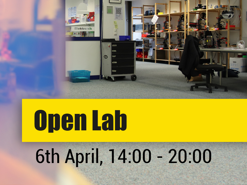
Wir melden uns mit guten Neuigkeiten! Das Fab Lab öffnet seine Pforten ab Semesterbeginn endlich wieder. Wir freuen uns also, euch den Termin für das nächste Open Lab verkünden zu dürfen: Mittwoch, der 06. April.
In Anbetracht der nach wie vor sehr hohen Corona-Fallzahlen haben wir für BesucherInnen des Labs allerdings ein paar Empfehlungen:
Innerhalb unserer Räumlichkeiten empfehlen wir die 3G Regel beizubehalten (genesen, geimpft, getestet). Weiterhin ist empfohlen durchgehend eine Maske zu tragen. Natürlich darf die Maske zum Trinken abgenommen werden, wir bitten aber darum, diese danach direkt wieder aufzusetzen. Aus diesem Grund sind aktuell auch offene Getränke (bspw. Kaffee/Teetassen) nicht gerne gesehen, da diese erfahrungsgemäß zu einem “Kaffeeklatsch” führen 😉 Statt direkt am Arbeitsplatz zu essen, bitten wir euch, eure Speisen an denoffenen (!) Fenstern in der Lobby bei Startpunkt zu konsumieren, um die Sicherheit aller Anwesenden zu gewährleisten.
Die BesucherInnen-Anzahl im Fab Lab ist auf maximal 20 Gäste beschränkt.
Zusammengefasst:
maximal 20 Gäste im Lab
3G empfohlen (genesen, geimpft, getestet)
um durchgehendes Tragen der Maske wird gebeten (Ausnahme: Trinken und Essen in bestimmten Bereichen)
In Anbetracht der aktuellen Inzidenzen haben wir zu unser aller Sicherheit beschlossen, das Fab Lab bis auf weiteres geschlossen zu halten.
Ein fester Termin für eine Wieder-Öffnung steht derzeit nicht fest. Sobald das Pandemiegeschehen ein sicheres Open Lab wieder zulässt, werden wir dies hier auf der Website, per E-Mail und Social Media bekannt geben.
In dringenden Fällen, z. B. für die Arbeit an Abschluss- oder sonstigen Projektarbeiten, kontaktiert uns und wir finden eine Lösung.
Vor dem Hintergrund des in den kommenden Wochen zu erwartenden Pandemieverlaufs hat die Universität Siegen ihre Maßnahmen angepasst. Alle Gebäude der Universität bleiben daher bis einschließlich zum 06.02.2022 für die Öffentlichkeit geschlossen. Wie es danach weiter geht, ist zum jetzigen Zeitpunkt noch nicht bekannt.
Für das Fab Lab bedeutet das, dass bis mindestens zum 06. Februar kein Open Lab stattfinden wird. Entgegen unserer letzten Aussage findet dementsprechend auch kein Open Lab am kommenden Mittwoch, den 19. Januar statt. Wir hoffen, dass wir euch am 09.02. wieder bei uns begrüßen dürfen, können dies derzeit aber noch nicht versprechen.
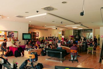
Finally the time has come, from Wednesday, October 13 we open once a week on Wednesdays from 2 to 8 pm. We are very excited to welcome you to the new Lab at Sandstraße 26, on Reichwald’s corner, and to work (and drink mate) with you again.
The 3G rule applies, which means whoever is vaccinated, recovered or tested negative may come by. However, seating is limited to a maximum of 20 people at any one time. Masks are mandatory throughout the Lab (except at the workplace) and safety distance. Use of the Fab Lab is still free, but as always, everyone brings their own consumables.
It is also important that everyone, including those who have worked in the lab before, must take a safety instruction. Therefore, we are offering additional safety instructions on October 13 at 2 p.m., 4 p.m. and 6 p.m.. After that, there will be regular safety instruction on Wednesdays only at 4 p.m.
As usual, you don’t need to register or pay anything for the visit or the safety briefings.
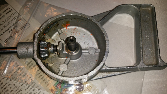
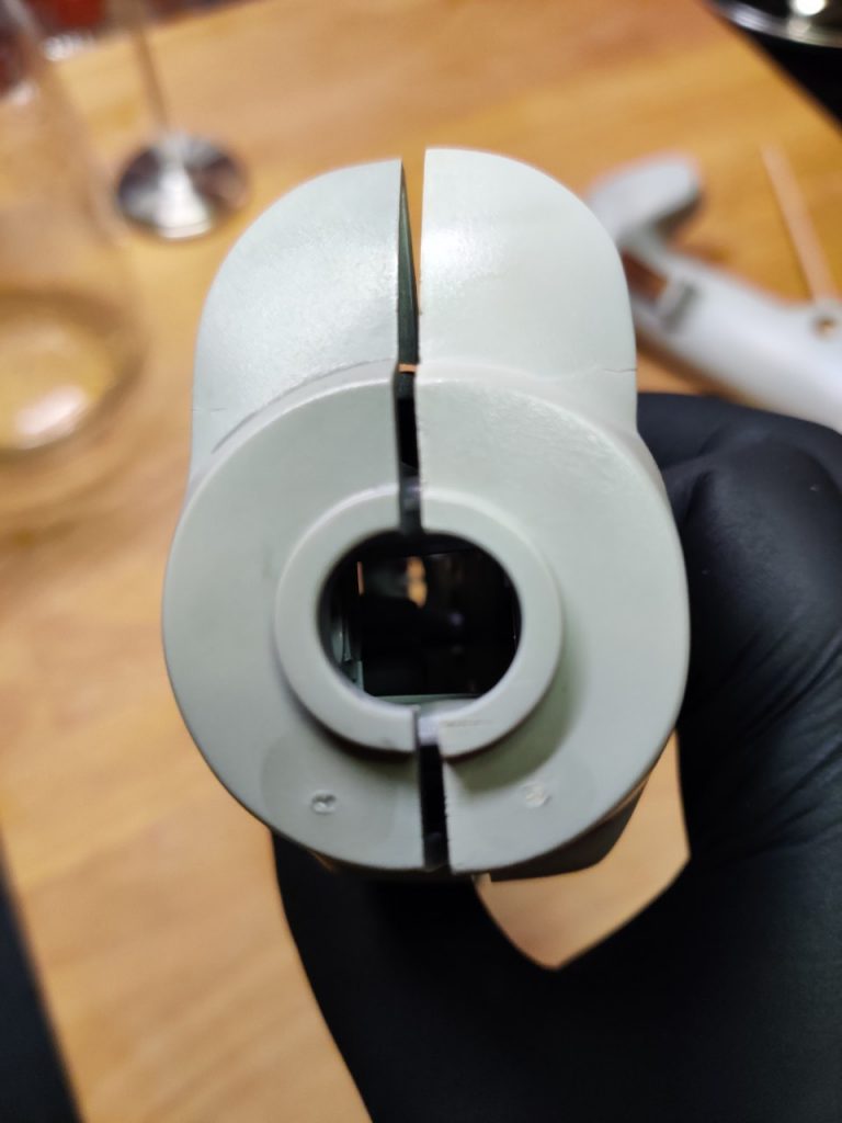
My father bought the thing at the flea market sometime. The price of 5 rubles (Ц. 5Р.) is incorporated in the handle, because at that time in the Soviet Union there was the planned economy and you could get a pack of butter for the same price in the big whole country.
Problem
The drill always did its job. It is particularly suitable for small jobs and you can dose the torque manually. Only at some point the drill got stuck somewhere and my father exerted too much momentum on the big bevel gear until a few plastic teeth sheared off, rendering the thing useless. The old bevel gear consisted of two parts: The front side with the teeth was made of a plastic casting and the back side was made of some kind of metal, which was somehow connected to the plastic (unfortunately no photo). So a new bevel gear was needed.
Solution
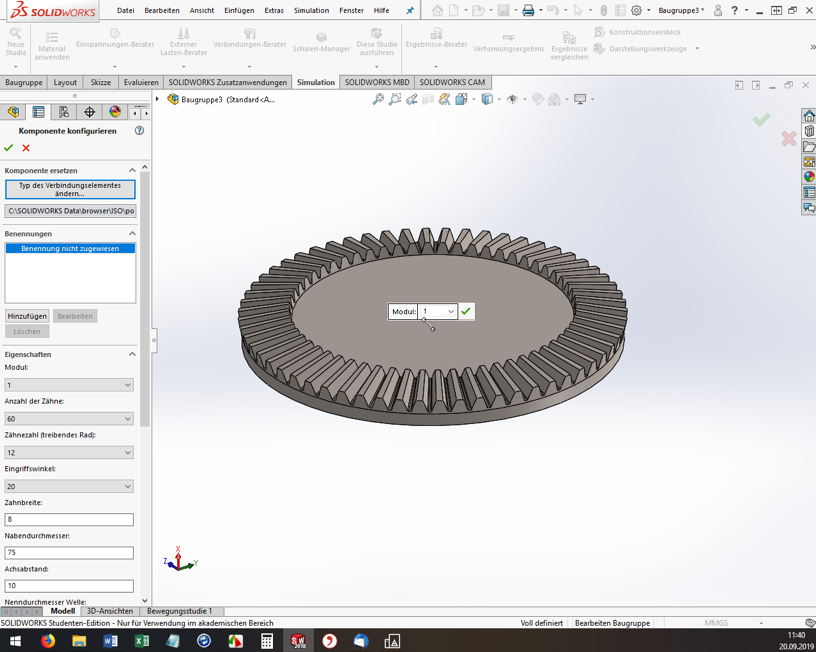
First, the teeth of the bevel gear had to be counted. There are 60 teeth. The driven bevel gear has 15 teeth, so there is a ratio of 1:4. In addition, all dimensions, such as the height of the teeth, their width and the bore diameter of the bevel gear had to be measured with a caliper gauge. The problem: the teeth are not simply arranged in a straight line, and their “focal point” is somewhere in the air. They are also wider at the outermost diameter than at the inner diameter of the bevel gear. So the geometry is a real challenge and you can’t just build the thing with a CAD program if you’re not a professional.
But what to do? Fortunately, I happened to come across a solidworks tutorial on the internet. It shows how to create configurable standard parts using the solidworks (SW) design library. And that worked well!
Procedure
Open Solidworks, open any assembly and throw out all the parts. Somehow it didn’t work out any other way for me. Then, on the right side of the screen, open the construction library and shimmy through the tree. Toolbox, ISO, power transmission, gears, degree bevel gear (driving).
For me, the ISO standard matched well with my Soviet part. Then the “Degree bevel gear (driving)” must be dragged and dropped into the assembly window. Now the “Configure component” dialog opens on the left. The module, the number of teeth, the pressure angle, etc. can be set. Here you have to experiment, have the bevel gear with the green check mark built again and again and measure it. (Tip: If you click on a component edge, the bottom info bar of SW conveniently shows the measured length directly).
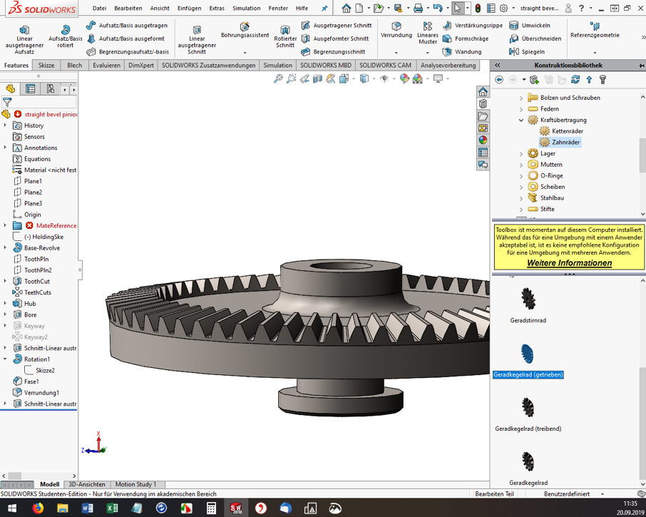
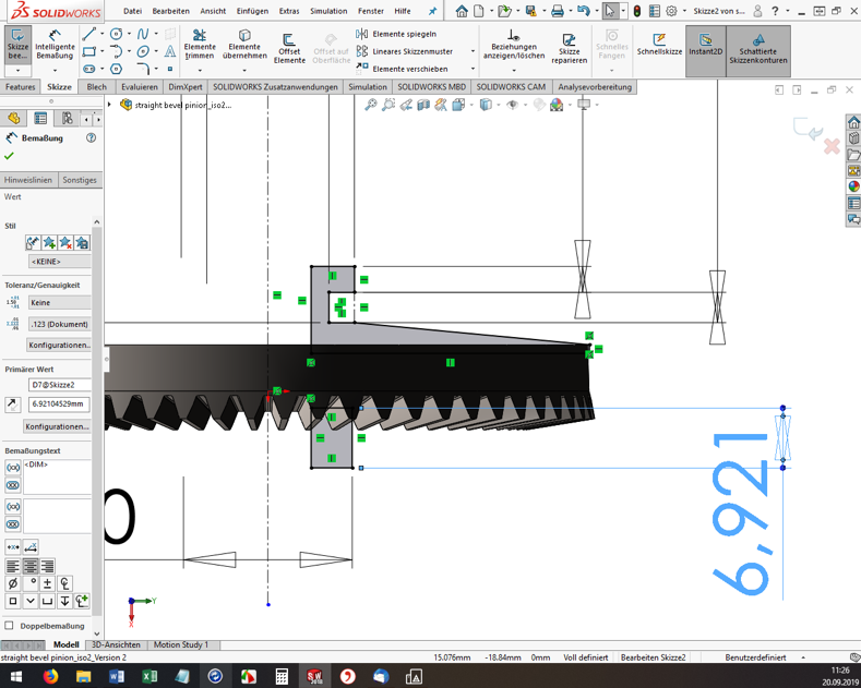
However, you cannot specify all dimensions and geometry properties in the configurator. And here’s where it gets a little tricky. If the tooth geometry of the blank created fits so far, the rest must now be added manually. I used the function “Attachment/Base rotated” to build a created sketch as a body of rotation to the blank (see screenshot). Again, I had to measure the old bevel gear over and over again.
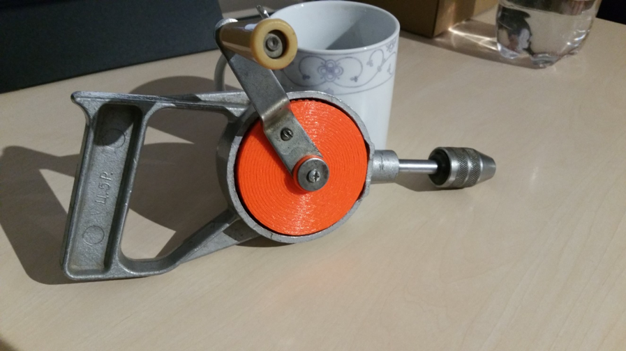
Once you are satisfied with the part, you need to export it to *.STL format for 3D printing. And off we go to the Fab Lab Siegen! Here Fabian helped me out, showed me the 3D printers and started the printing. Thanks a lot! 😊
Result
The first print was unsuccessful (of course). In 3D printing, for example, the holes are always slightly smaller compared to the model. The teeth were also too small, so that they could not engage deeply enough with the opposing teeth. These teeth also sheared off during initial attempts. In addition, the bracket for the crank was a bit too thin and is therefore broken off.
But now it was possible to measure the printed bevel gear and improve the dimensions in SW and finally start a second attempt. However, the second time it went better than expected and the bevel gear installed beautifully. The hand drill runs very smoothly and if any problems should occur in a few years, I’ll just print out the bevel gear again 😉 .
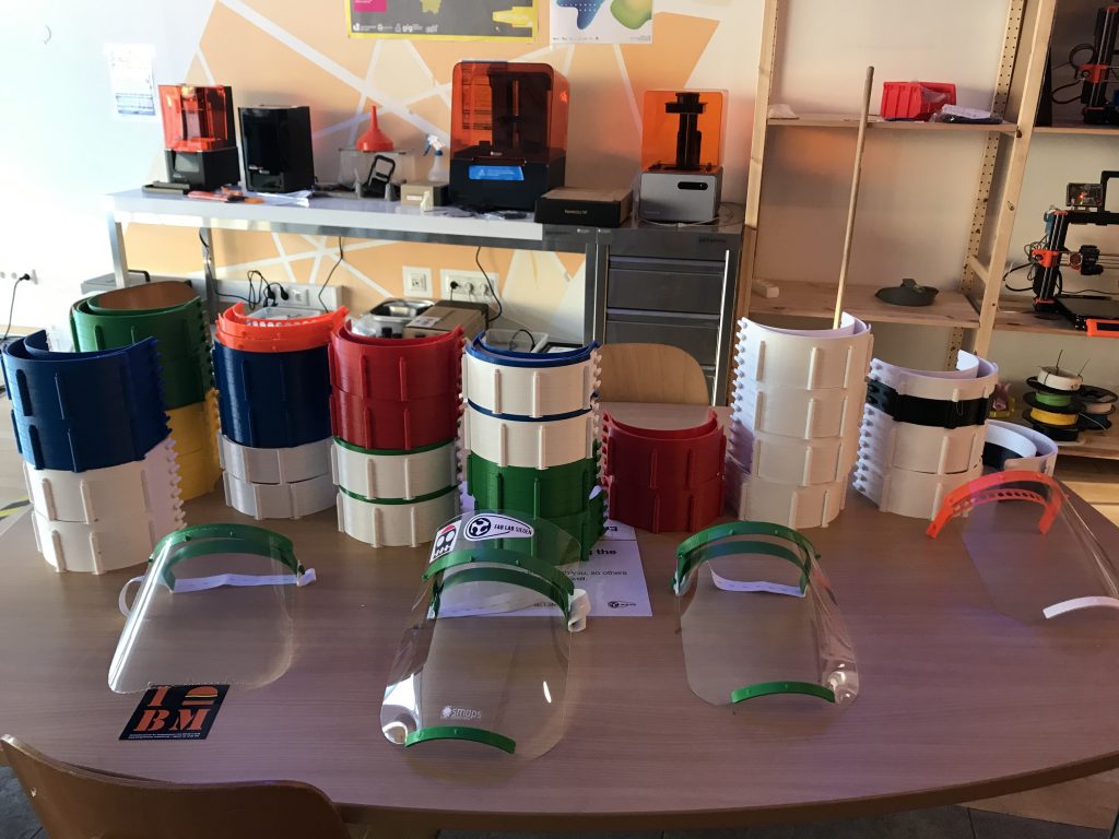
After the closure is before the start of production. After all, we, like many other public institutions, had to cease our operations on March 16. Now there were a dozen 3D printers standing around unused. MakerVsVirus and other ideas and projects that developed online in the following days invited us to do something against the virus.
Well, to make a long story short, we are now producing facial visors to reduce the risk of infection to medical personnel and other at-risk groups(the hip girls and guys also call them covid shields). The visors are given free of charge to medical facilities.
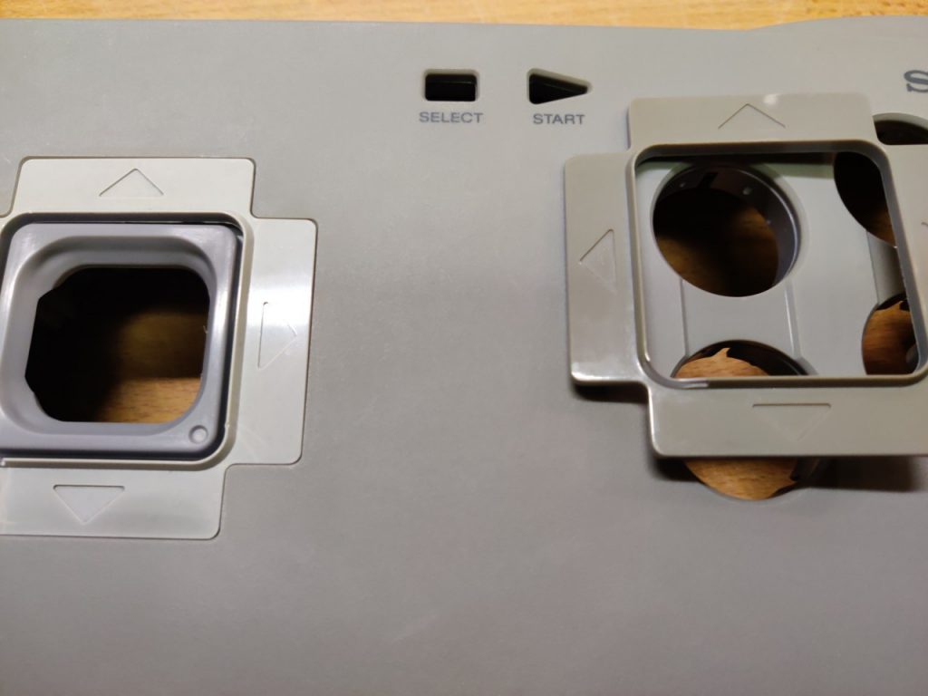
In the last two days I have been working on retr0bright and I don’t want to withhold my experiences from you. I’m currently retrofitting this old Playstation 2 controller and was actually going to limit myself to the inside, but now I’ve decided to give the controller a bit of a facelift on the outside as well.
However, the primary goal was not to make the controller look nicer again, but to simply have retr0bright done. So I looked around in this internet how retr0bright works and what you need for it. You can find many different recipes and procedures. All involve hydrogen peroxide (H2O2) solution 👨🔬 and (UV) light. I was inspired by this video first and decided on the H2O2 and heat variant:
For this I bought a 3% hydrogen peroxide solution. You can get them for a few euros at Müller or Amazon. To test the procedure, I first performed a small test. There were two parts on the controller that had to be replaced due to damage and could therefore be used as a test and reference object. Before the test, I removed the protection from the parts.
For the H2O2 & heat variation, I mixed the H2O2 with tap water in about a 1:2 ratio and heated it to about 60°C in a pot, then let the first part float in the solution for four hours. Even though no additional light source was used in the video, I still decided to shine a lamp into the pot. Since other tutorials keep saying that the best results can be achieved with ultraviolet light or lots of light in general, I took the brightest/intensive lamp I had there. This is a 50W high power LED which is normally used as plant lighting. But I can’t tell you exactly what wavelength comes out ¯_(ツ)_/¯.
After four hours, I then took the part out of the solution and could perceive a visible brightening, with which I was satisfied.
So in go the next parts. Since I had bought only a small bottle of H2O2 (250ml) and accordingly there was not so much liquid in the pot, I first put in only the front sides of the joysticks, since they are somewhat flatter. Important: the parts should be completely covered. After four more hours, I took out the fronts of the joysticks and compared them to the backs.
I treated the backs using the same process, but I had to improvise a bit because I didn’t have enough of the hydrogen peroxide solution to completely cover the backs. So I decanted the solution into the jar and added some more water and then heated the solution by water bath. This time I couldn’t set up the lamp properly, so I left it out.
After another four hours, I got the parts out. The whitening was much less than the other pieces, so I just let them float in the solution for another three hours. Unfortunately, this did not bring so much.
Black gloves = professional.
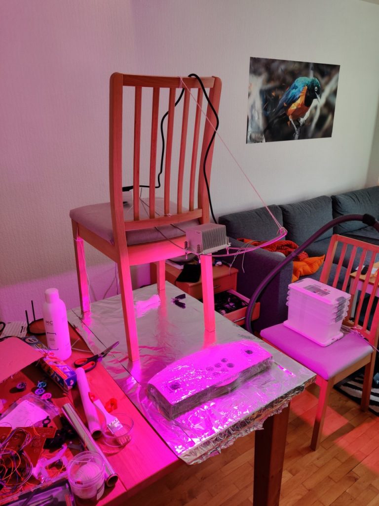
Since the actual controller housing is way too big for my pots, I used a different variant here. For large housing parts, the Internet recommends the use of hydrogen peroxide gel. In this process, hydrogen peroxide is mixed with glycerin (among other moisturizing properties) and xanthan gum (E 415, thickening agent). Alternatively, you can use Oxide Cream from the hairdresser: https://www.amazon.de/Cream-Oxide-1000ml-12/dp/B008F5MIL6/ (see reviews).
The procedure here is as follows: The part to be bleached is evenly coated with the gel and then, if possible, wrapped airtight (zip lock bag or cling film) and placed in the sun or under a lamp for about 24 hours. Wrapping is to prevent the gel from drying out too quickly.
The aluminum foil serves only as protection for the table. Then quickly built a bracket for the lamp 👨🔧.
After about 24 hours, I then freed the case from the cling film and washed it properly. It has become brighter, but unfortunately not as much as the other parts.
BeforeAfter
I also put the backs of the joysticks under the lamp overnight. In the morning, the parts looked like this:
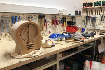
A photo series was created from a plaster face mask.
A point cloud from the photo series was created with Linux/Colmap.
The points were cleaned up and processed with Meshlab
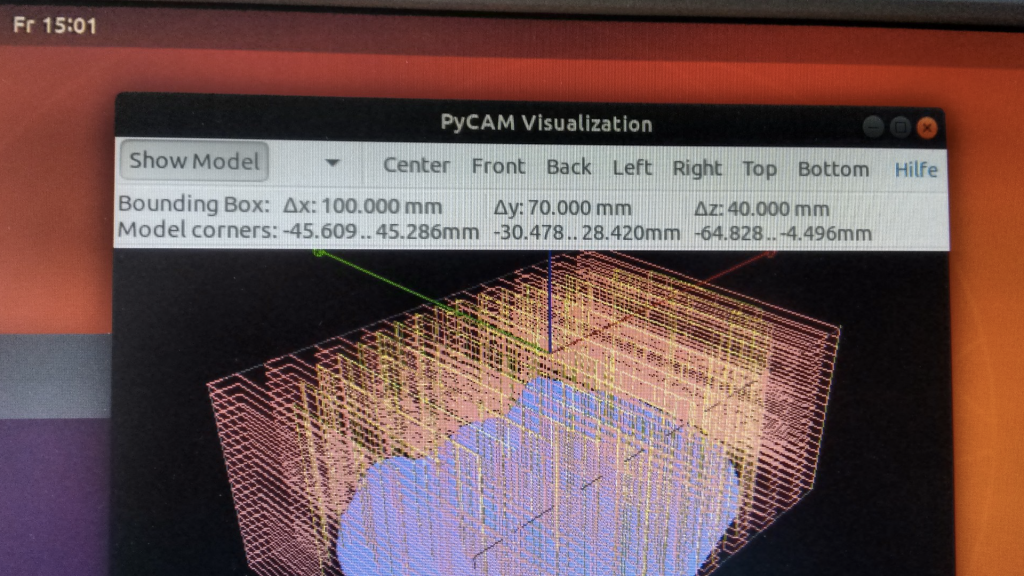
The milling paths were generated with Pycam.
The toolpath files were created with a tool developed in-house.
simplified so that the GCode can be run with the Fablab CNC software as well as NCcad.
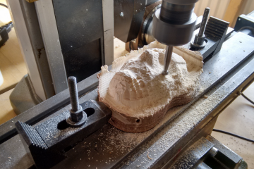
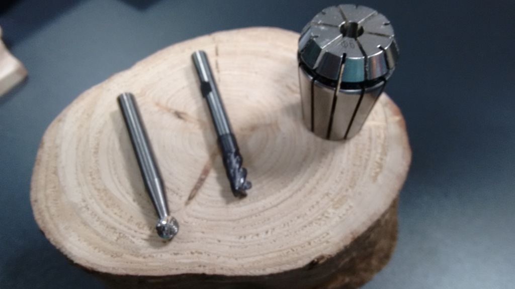
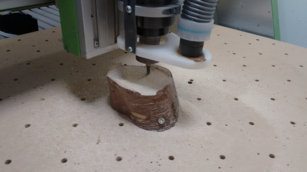
The workpiece: a 1 1⁄2 year old, dried piece of end-grain wood, pre-drilled for “spaxing” onto the sacrificial plate.
Cutter: 6 mm cylinder for “roughing” and 6 mm spherical head for “finishing”.
About The Manufacturing Process
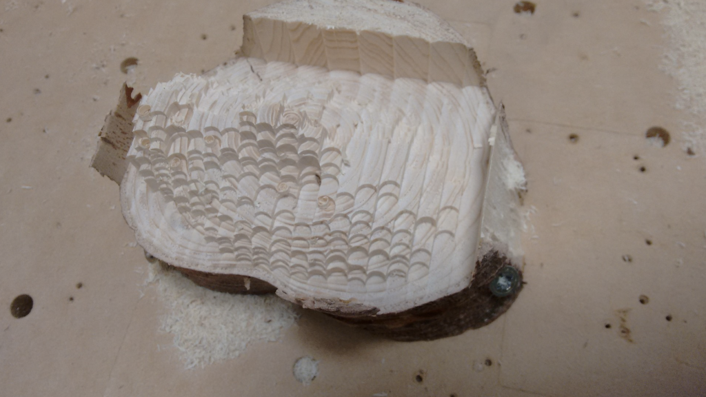
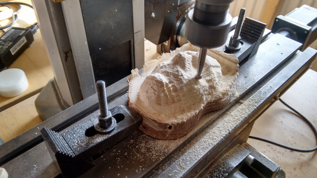
The feed rate for milling could be increased significantly. The cutter length was not sufficiently taken into account during the creation. This is how the saying of the day came about: “One more delivery is possible”. Before any collisions occurred, it was stopped. After remodelling and x-times finishing (Proxxon), the following emerged:
This project was kindly supported by the University of Siegen. Many thanks for this, especially to Daniel for his collaboration and Helga for text drafting and layout.
Remark: Only a very slow Linux notebook (Ubu 19.04) is available on site. (possibly faster with SSD or cloud computing ??) Network access for updates planned. Friday afternoons are aggravating and not so well suited for such projects with public traffic and the limited time of the staff. Other spax screws are missing or have not been found. The cutter selection is limited. Unsolved : Chatter marks.
On Thursday (13 February) Christian will give a talk about Fab Lab Maya at 7pm. Christian visited Fab Lab Maya in the Mexican jungle and would like to tell us about it. There they try to support the local population and traditions with modern technologies. The title of the lecture is “FabLab Maya – Can technology help to preserve traditions?
We can now offer you new opening hours for the Lab! Friday remains in place. We are also open on Wednesdays and Saturdays. We would also like to take this opportunity to remind you of our safety briefings twice a month and our plenary once a month. The 3D Printing Happy Hour merges into the Wednesday appointment and no longer exists in its own right.
The opening hours are valid until we move out of the Herrengarten.
New Opening Hours
Wednesdays: 13:00 – 17:00
Fridays: 14:00 – 20:00
Saturdays: 12:00 – 18:00
At these times, work can be done freely in the Fab Lab. All interested parties are welcome to attend. We are looking forward to your visit! If you want to work in the Fab Lab, you must have taken part in an appropriate safety course beforehand.
Important: We may have to cancel opening hours from time to time due to other events or teaching at the Lab. But then we’ll announce it beforehand! So before you go to the Lab, check here on this page to see if it’s really open.
Safety Instructions
Safety instructions are held at 4 p.m. every first and third Thursday of the month. Registration is not necessary. Read more here.
Plenary
On the last Thursday of the month we have our plenary for everyone at 5pm. More Information here. Just come by.